HYDRO. DRIVE AND BRAKE SYSTEM
36
Neutral control adjustment
NOTE: Neutral control rarely goes out of adjust-
ment on its own. If it needs adjustment, check for
damaged linkage or signs of tampering.
CAUTION: The tractor engine and drive system
must be operated to complete this procedure.
Confirm that no hazards will be incurred by run-
ning the engine or operating the drive system:
• Work in a well vented area to prevent carbon
monoxide poisoning or asphyxiation.
• Be careful to avoid contact with hot parts or mov-
ing parts.
1. Loosen the wheel bolt or lug nuts on the right
rear wheel of the tractor.
2. Lift and safely support the rear of the tractor.
3. Remove the right rear wheel:
• LTX tractor drive wheels fit on a “Double-D”
axle, and can be removed using a 1/2” wrench.
• SLTX tractor drive wheels are hub mounted.
Remove the lug nuts using a 3/4” wrench.
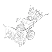
4. By-pass the seat safety switch. See Figure 5.17.
4a. Remove the seat from the tractor.
4b. Disconnect the seat safety switch.
NOTE: This procedure is described in Chapter
4: Body Panels.
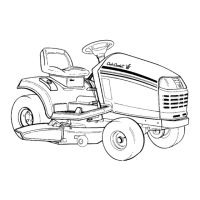
5. Confirm that the linkage is in the neutral position:
The roller on the control arm must be centered in
the “elbow” of the control cam. See Figure 5.18.
• If the roller is not centered in the elbow of the
control cam, identify and correct the problem
before proceeding.
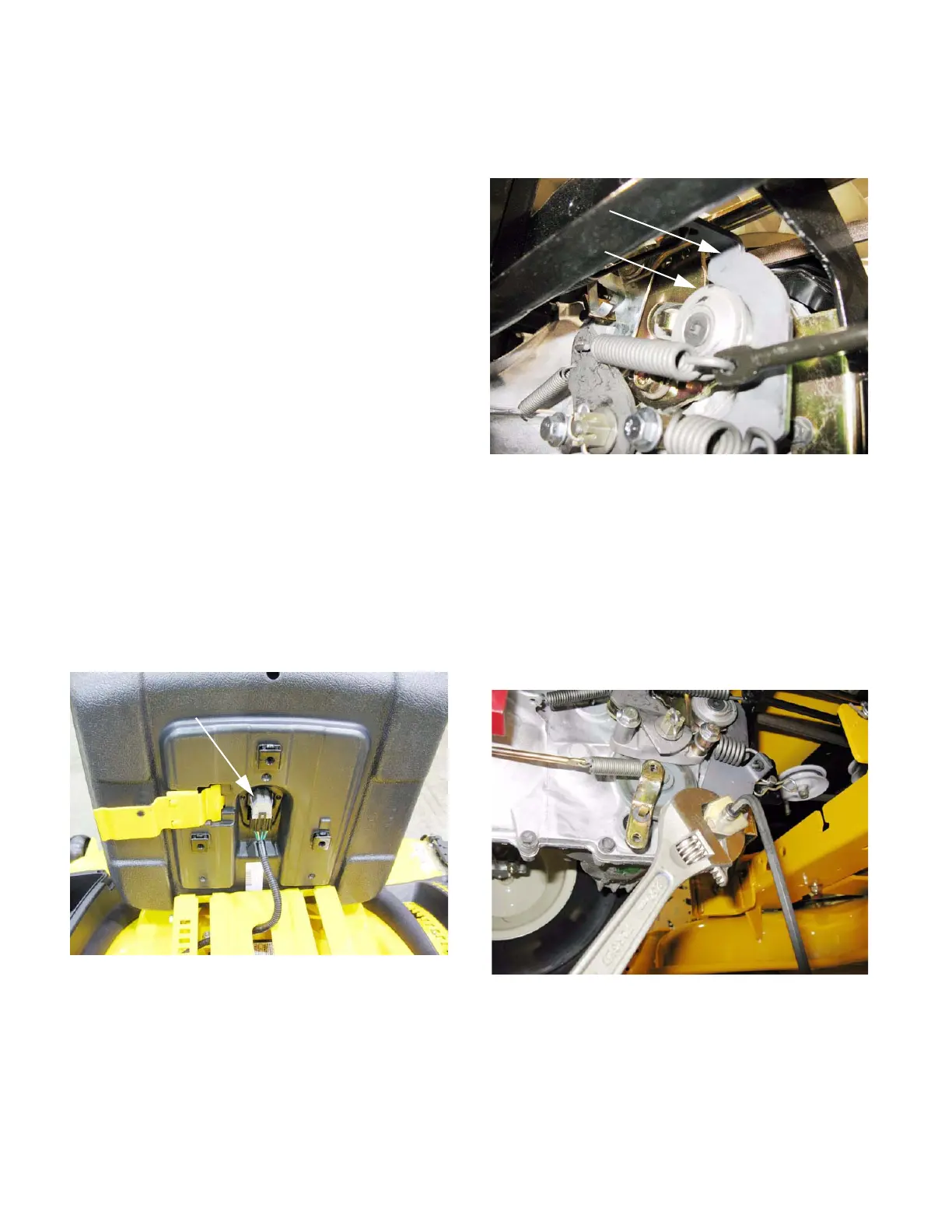
6. Loosen the socket head cap screw that locks the
adjusting puck using a 1/4” allen wrench.
7. Have a 1-1/8” wrench handy, or size an adjust-
able wrench to fit the adjusting puck.
See Figure 5.19.
8. Start the engine and advance throttle to maxi-
mum RPM.
9. Set the adjusting puck so that neither wheel
rotates.
The brake rotor should also be stationary.
Figure 5.17
Seat safety switch
Figure 5.18
Cam
Roller
Figure 5.19
 Loading...