BODY PANELS
18
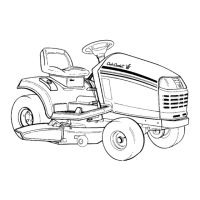
Hood components: pivot bracket removal
1. Remove the four screws that hold the outer arms
of the pivot bracket to the hood using a 3/8”
wrench. See Figure 4.11.
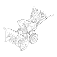
2. Remove the two screws that hold the pivot
bracket and grill to the hood assembly using a 1/
2” wrench. See Figure 4.12.
3. Assemble and install the grill by reversing the
steps used to remove it.
• Tighten the small screws to a torque of 15-35 in-
lbs. (1.7-4.0 N-m).
• Tighten the large screws to a torque of 25-45 in-
lbs (2.80-5.1 N-m).
Seat and Fenders
CAUTION: The battery will be removed in this
procedure. Review the Operator’s Manual and
the Chapter 7: Electrical Systems for important
safety information about handling batteries
before proceeding.
There are four variants of fender used on the Cub
Cadet Series 1000 for the model year 2009 and after:
• Manual PTO models have two levers on the
right fender: one for the deck height control and
one for the PTO.
• Electric PTO models have one lever on the right
fender to control the deck height.
• CVT-drive tractors (single-speed transmission +
variable speed pulleys) use fenders with a single
pedal opening on each side: clutch/brake on the
left, drive pedal on the right. In addition, a for-
ward-neutral-reverse lever is on the left fender.
• Hydrostatic-drive tractors use fenders with a
single pedal opening on the left, and two open-
ings on the right. The clutch/brake pedal is on
the left, with two pedals on the right; one to con-
trol forward drive, and the other to control
reverse drive.
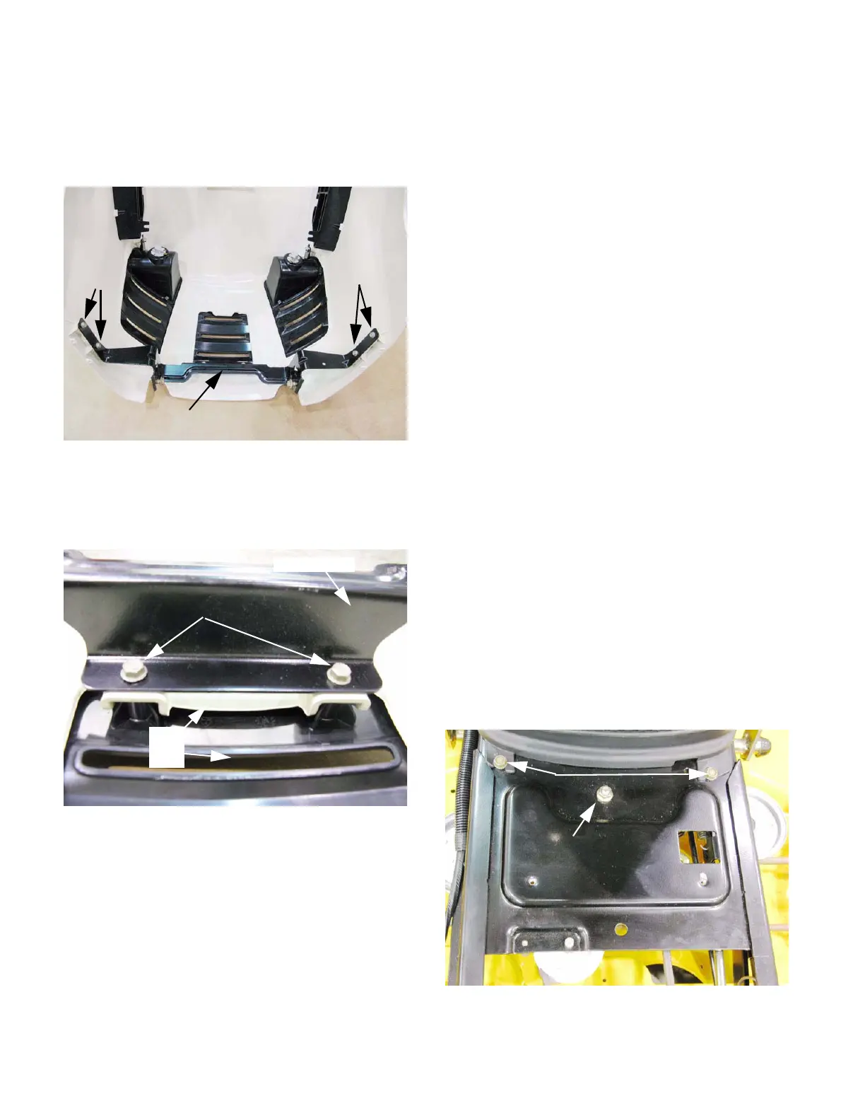
NOTE: Removing the fenders makes access to:
• The bolts that hold the base of the dash panel to
the frame. See Figure 4.13.
• The nut that holds the drive belt tensioner pivot
bracket to the frame.
• The travel stop pin that must be taken-off to
remove the control pedal cross-shaft.
Figure 4.11
pivot bracket
Small
screws
Small
screws
Figure 4.12
Pivot bracket
Large Screws
Hood
Grill
Figure 4.13
Drive belt tensioner
bracket pivot bolt
Dash
mounting
bolts
 Loading...