Cutting Decks And Lift Shaft
142
2. Measure the distance from the front of the blade
tip to the ground and the rear of the blade tip to
the ground.
NOTE: The front measurement taken should be
between 1/4” - 3/8” less than the rear measure-
ment. Determine the approximate distance nec-
essary for proper adjustment and proceed, if
necessary, to the next step.
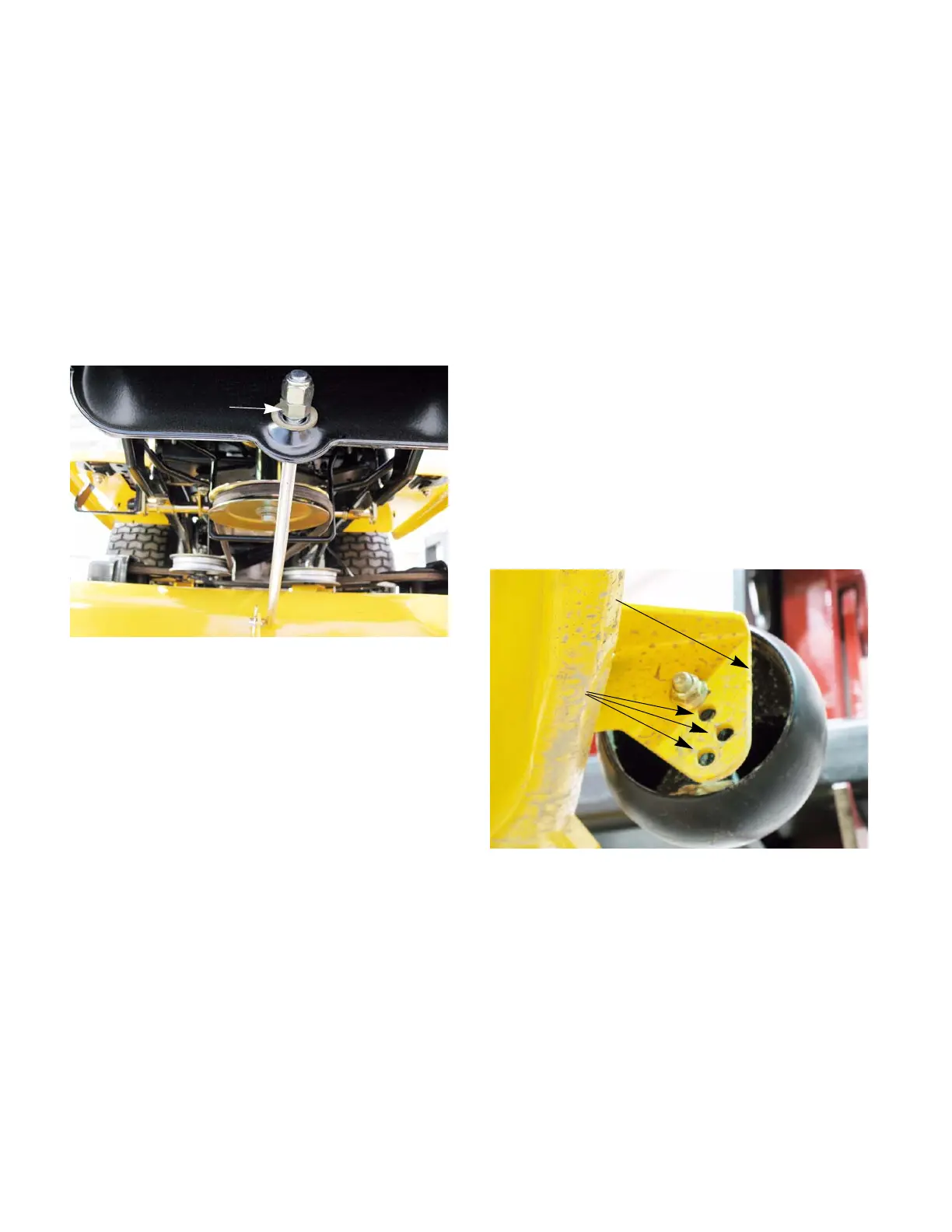
3. Working at the front of the tractor, loosen the two
hex lock nuts at the front of the deck hanger rod.
Thread the lock nuts away from the hex nuts
behind them. See Figure 8.29.
NOTE: Both nuts are on the top side of the
bracket to float and rise if the deck impacts
something. This helps to minimize the damage
to the deck
4. Using a wrench, turn the inner hex nuts clock-
wise to raise the front of the deck, or counter-
clockwise to lower the front of the deck.
5. Retighten the two hex lock nuts when properly
adjusted.
Deck Wheel Adjustment
The cutting decks are of a “floating” design. This
means that they are suspended above the ground. The
gauge wheels occasionally touch the ground. They are
designed to bump the deck up and over irregularities.
This helps prevents scalping damage to the turf and
damage to the deck.
Adjust the wheels as follows:
1. Place the tractor on a smooth, flat surface and
move the deck to the desired mowing height
using the deck lift lever.
2. Check gauge wheels distance from the flat sur-
face below. If the gauge wheels contact the
ground, they must be raised. If the wheels are
higher than 1/2" above the ground, they should
be lowered.
3. Remove the shoulder bolt securing the one of
the front wheels to the index bracket.
4. Reposition the wheel to align with the one of four
index holes that places the wheel 1/4" to 1/2"
above the ground. See Figure 8.30.
5. Secure the wheel to the index bracket with the
shoulder bolt. Note the index hole used and
secure the other wheel in the same position.
6. Repeat the previous steps on the rear wheels.
Figure 8.29
The two nuts
Figure 8.30
Index holes
Ball wheel
 Loading...