ELECTRICAL SYSTEM
114
Amperage: Most DMMs have a very limited capacity
to test amperage (2-3 Amperes). When measuring cur-
rent flow, the meter must be connected in series with
the component to be measured. That means opening
the circuit and having the circuit go through the meter.
• Some meters have an inductive “Amp clamp”
accessory that can be used without breaking the
circuit.
• Testing amperage beyond the capacity of the
meter can burn-out an internal fuse in some
meters. The fuses can be expensive.
Resistance: Set the meter for the “Ω” scale.
• Isolate the part of the circuit to be tested (discon-
nect it from the source of power).
• Ohms are read on a scale of 0 to 1, with “0” indi-
cating no resistance and “1” indicating infinite
resistance.
• Most auto-ranging meters will provide readings
on several scales. For outdoor power equip-
ment, the straight Ohm scale is most appropri-
ate. If a letter appears next to the W on the
screen of the DMM, it indicates different scales
of sensitivity.
“m” is micro-Ohms (.001 Ω), a more sensitive
scale that effectively moves the decimal point
three places to the left of its location for plain Ω
“K” is Kilo-Ohms (1,000 Ω), a less sensitive scale
that effectively moves the decimal point three
places to the right of its location for plain Ω
“M” is Meg-Ohms (1,000,000 Ω), is the least sen-
sitive scale that effectively moves the decimal
point six places to the right of its location for plain
Ω
• A reading of “0” may be called “Continuity”.
A reading of “OL” may be referred to as “No
Continuity”.
• Mistaken Ohm readings most frequently come
from bad technique. Poor connections between
the probes and the point to be read can throw-off
readings. False readings can be generated if the
technician touches both probes with their fingers
while taking the reading.
• The meter has it’s own power source to measure
resistance. Connecting the meter to a compo-
nent that has current going through it will dam-
age the meter (usually beyond repair).
Wiring diagram or schematic
• A wiring or a schematic diagram, and the ability
to read it are very important in troubleshooting a
circuit. The diagram shows how the circuit was
designed and what paths the electricity is sup-
pose to flow.
Fused jumper wires
• Fused jumper wires are handy to help find bad
grounds or to jump across switches for testing
purposes.
CAUTION: Only use fused jumper wires. If there
is a short in the circuit, using an unfused jump
could damage components in the circuit.
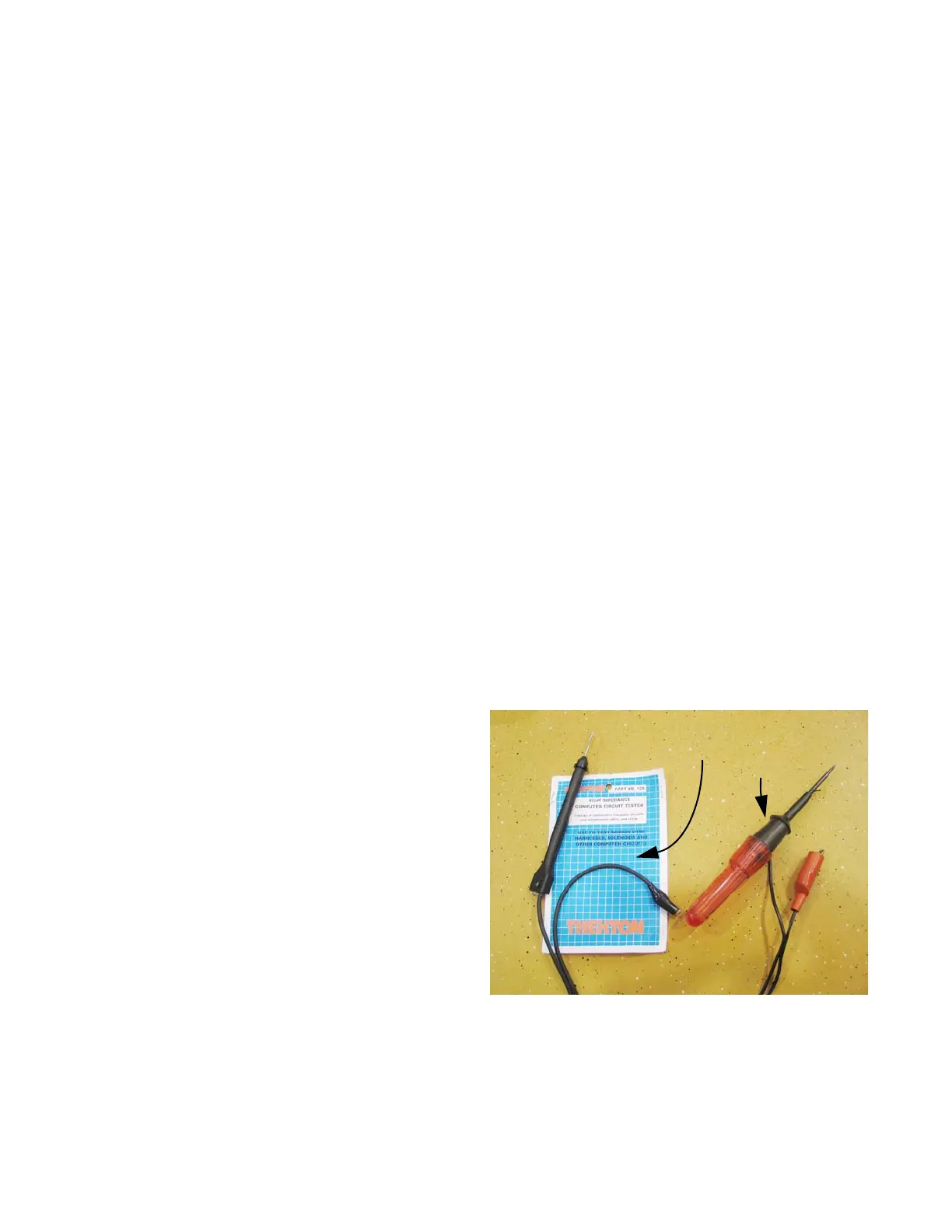
Test lights (high impedance)
• Test lights are used as a quick way to verify volt-
age at a point in a circuit. Like DMMs, they come
in a wide variety from many manufacturers.
• The most basic test lights simply use the current
being checked to light an incandescent lamp.
These should not be used on any equipment
that has or may have solid-state circuitry.
The power necessary to light the bulb is more
than many solid-state circuits were designed to
handle. Components will be destroyed in the
process of testing them. See Figure 7.32.
NOTE: Do not use a test light on a 900 series
tractor. It can damage the RMC module.
• If a test light is used at all, it should have “high-
impedance”, indicating that it only takes a sam-
ple of the electricity being tested, and illuminates
an LED to indicate the presence of power.
Figure 7.32
Hi impedance test light: Incandescent
GOOD test light:
BAD
 Loading...