ELECTRICAL SYSTEM
126
Testing switches
• Refer to the “Components” section of this chap-
ter that describes the function of the individual
switches to be tested.
• Switches can be tested “hot” by looking for volt-
age at the appropriate posts. This is not defini-
tive, since the source of the voltage is not always
confirmed. Checking for voltage does not work
on switches that work by providing a ground
path to the magneto primary windings or a solid
state control device.
• The most valid way to test switches is a continu-
ity test.
• Understand the internal functions of the switch.
Key switches and PTO switches can be fairly
complex.
1. Isolate the switch from the rest of the circuit.
2. Test each pair of terminals for continuity in all
modes of switch operation: at-rest, and actu-
ated.
• Many switches on Cub Cadet equipment are
typed by their at-rest state: Normally Open, Nor-
mally Closed, Common.
• Normally Open (N.O.) contacts do not complete
a circuit when the switch is at-rest (plunger
extended). They close to complete a path
through the switch when the plunger is
depressed.
• Normally Closed (N.C.) contacts complete a cir-
cuit when the switch is at-rest (plunger
extended). They open to break the path through
the switch when the plunger is depressed.
• Some Cub cadet switches contain more than
one pair of contacts. The same switch housing
can contain normally open and normally closed
switch elements.
• When testing a switch that contains more than
one set of contacts (elements), the male spade
terminals associated with Normally Closed con-
tacts will be stamped “N.C.”
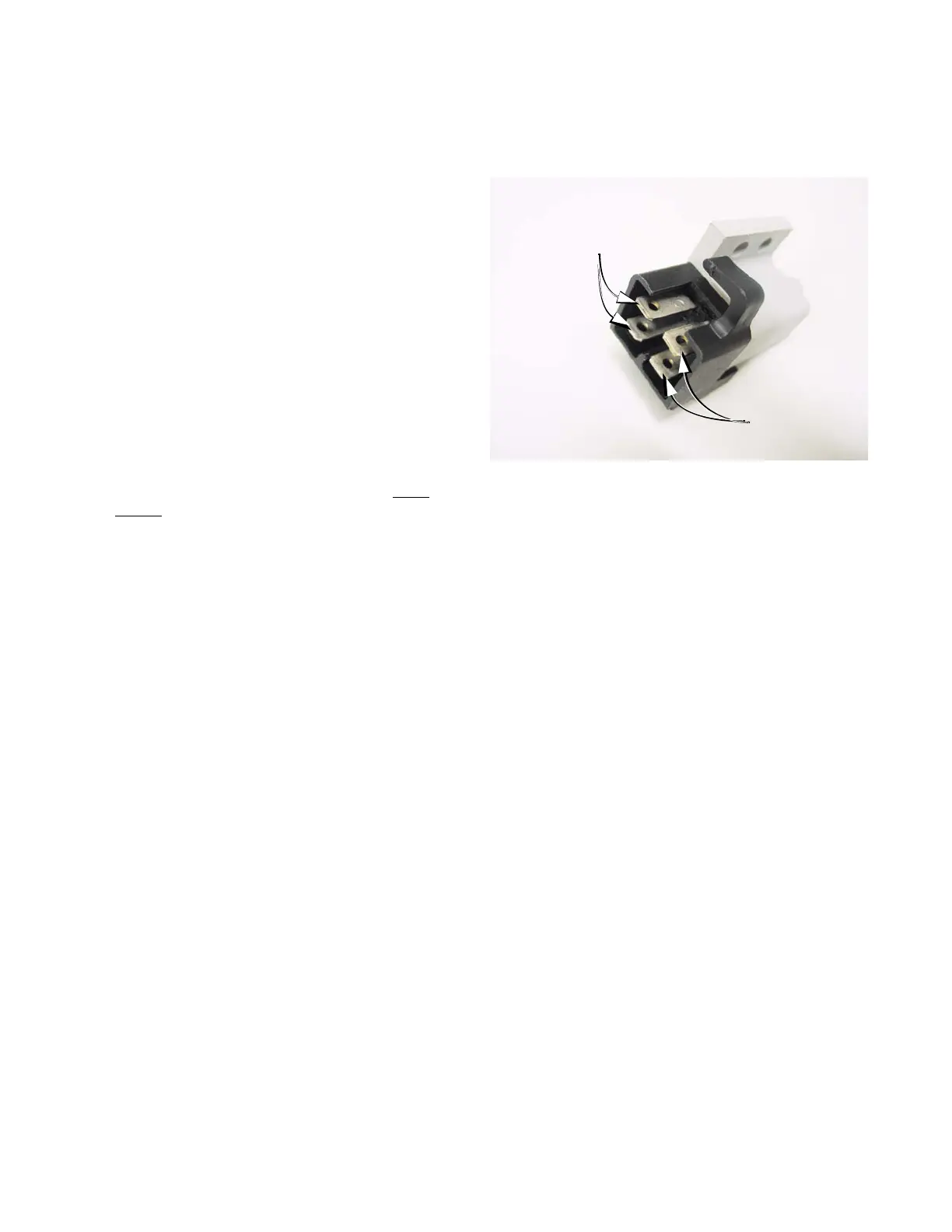
• The male spade terminals that are associated
with each-other face each-other broad-surface
to broad surface. See Figure 7.52.
Figure 7.52
Normally Closed
switch element:
Spades marked: “NC”
Normally Open
switch element:
Spades blank
 Loading...