HYDRO. DRIVE AND BRAKE SYSTEM
51
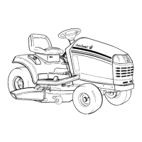
7. With the brake yoke removed, the brake rotor
floats on a splined brake shaft. See Figure 5.69.
• The by-pass linkage must be removed to take
the rotor off.
• The flat side goes in, the collar faces out.
• A second brake pad fits into a recess behind the
rotor.
8. Assembly notes:
• If any lubricant is used on the pins or between
the brake shaft and the rotor, apply it VERY
sparingly.
• Apply a small amount of thread locking com-
pound such as Loctite 242
TM(blue) to the
threads of the brake yoke bolts.
• Tighten the brake yoke bolts to a torque of 80 to
120 in-lbs. (9 to 14 N-m).
9. Adjust and test the brakes after any work on
brake system.
Figure 5.69
Brake pad
Brake rotor
By-pass
arm
Transaxle removal and replacement
CAUTION: The battery will be removed in this
procedure. Review the Operator’s Manual and
the Electrical chapter of this manual for impor-
tant safety information about handling batteries
before proceeding.
1. Remove the mowing deck.
2. Set the park brake to release belt tension.
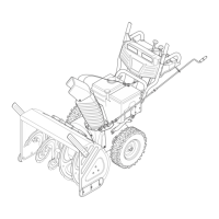
3. Remove the battery and battery tray, as
described in the body work chapter of this man-
ual. See Figure 5.70.
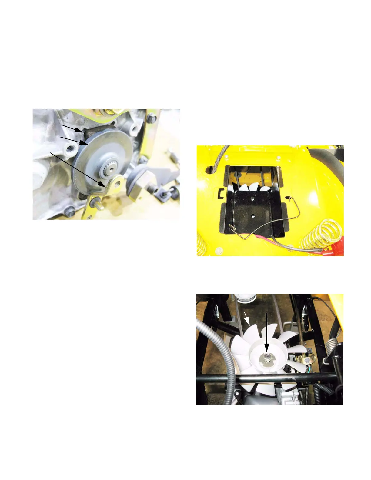
4. Remove drive belt from the transaxle pulley.
See Figure 5.71.
Figure 5.70
Figure 5.71
Fan Nut
 Loading...