CVT Drive and brake system
64
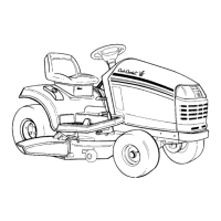
5. Remove and discard the cotter pin that holds the
plain end of the rod to the cobra head arm on the
pedal shaft. See Figure 6.18.
6. Pull both pedals (clutch/brake & drive control) all
the way back. Secure them with a shock cord if
necessary.
NOTE: The ball joint end of the rod will not come
out of the tensioner pulley bracket, but pushing it
up slightly makes it easier to adjust the rod
length.
7. Thread the rod into or out of the ball joint end to
lengthen or shorten it.
8. Adjust the rod so that the hole in the plain end
fits over the arm on the pedal shaft.
9. Install the lock-washer and nut on the ball-joint
stud, then re-check the adjustment.
10. Once the adjustment is correct, fasten the rod to
the arm with a new cotter pin.
11. Tighten the jam nut.
12. Test-run the tractor to confirm that the drive and
brake systems work correctly before reinstalling
the mowing deck.
13. Test run the tractor again after the mowing deck
is installed, and confirm that all of the safety fea-
tures work properly.
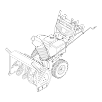
Linkage: pedal shaft
Description: The Clutch/brake pedal and the drive con-
trol pedal operate on two concentric shafts.
• The clutch/brake shaft runs the full width of the
tractor.
• The drive control shaft is tubular, and pivots on
the clutch/brake shaft.
• Each shaft has a toothed latch plate. The latch
plates are next to each-other.
• The cruise control/park brake lever operates a
common pawl that engages the latch plate of
whichever pedal is applied. See Figure 6.19.
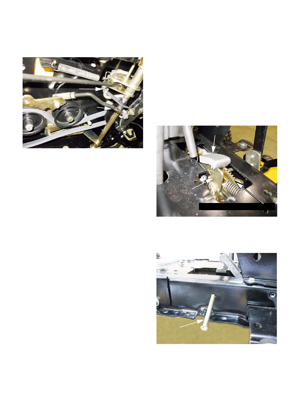
• A travel limit pin passes through curved slots in
both of the latch plates. The pin is blocked into
place by the fenders. See Figure 6.20.
Figure 6.18
Plain end
cobra head
Figure 6.19
Cruise / park
pawl
Clutch/brake
latch plate
Drive (cruise control) latch plate
Figure 6.20
Travel limit pin
 Loading...