HYDRO. DRIVE AND BRAKE SYSTEM
50
Brakes
NOTE: The brakes may be repaired in the trac-
tor, using procedures shown on the bench.
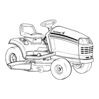
1. The brake yoke is located on the right side of the
transaxle. See Figure 5.65.
• The heavy actuator spring connects to the top
hole on the brake arm.
• The light return spring draws the brake arm to
the OFF position.
• Remove the cotter pin and loosen or tighten the
castle nut to adjust the brakes. Use a 9/16”
wrench to set a .015” (.381mm) gap.
2. There are two main reasons to remove the cali-
per: to replace the pads, or to free stuck parts.
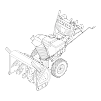
3. Loosen both brake yoke bolts using a 3/8”
wrench. See Figure 5.66.
4. Slip the return-to-neutral spring off of the spacer
on the front bolt.
5. The yoke and outer pad will separate from the
transaxle. See Figure 5.67.
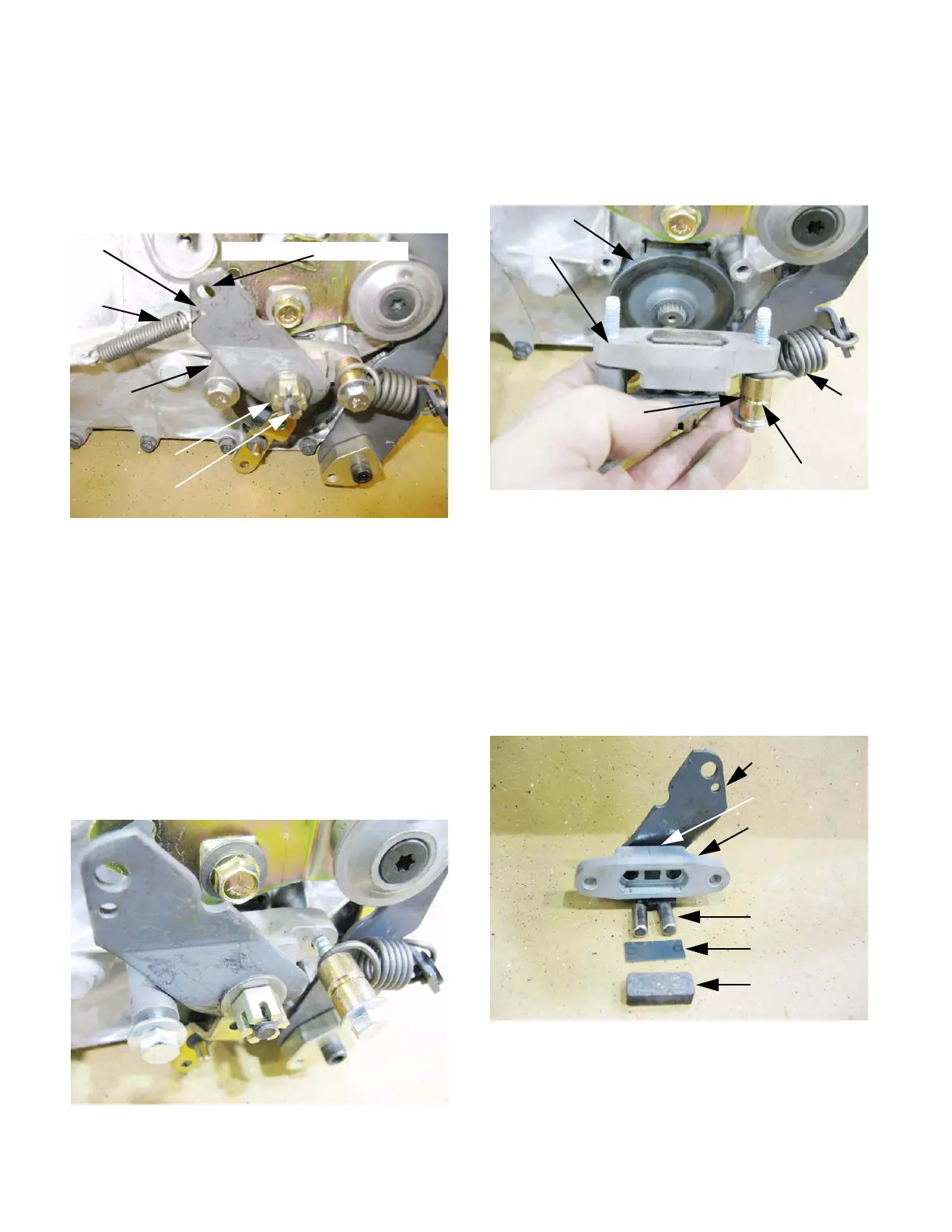
6. Inside the brake yoke;
• A steel backing plate fits between the friction pad
and the actuator pins.
• The pins fit into holes in the brake yoke housing.
• The brake arm acts as a cam, pushing the pins
when it rotates.
• A small compression spring pushes the cam arm
away from the pins, helping to release the brake.
Figure 5.65
Brake arm
Brake yoke
Return spring
Actuator spring hooks here
Castle nut
Cotter pin
Figure 5.66
Figure 5.67
Brake rotor
Brake yoke
Short r-t-n
spring
Grooved spacer
Installed r-t-n spring
fits into groove in spacer
Figure 5.68
Brake arm
Spring
Brake yoke
Friction pad
Backing plate
Actuator pins (2)
 Loading...