ELECTRICAL SYSTEM
127
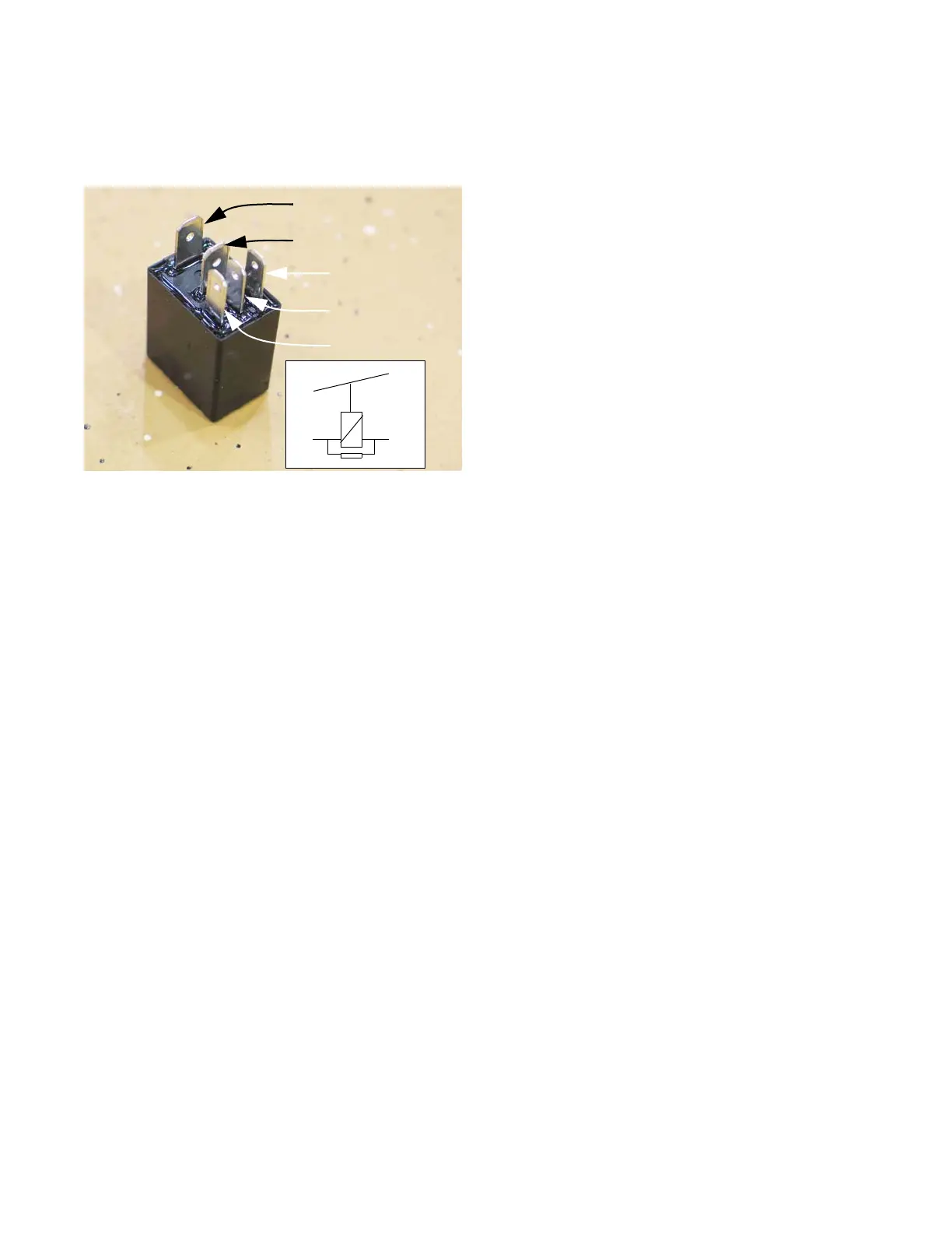
Relay
Most of the relays used by MTD or Cub Cadet have
five pins. See Figure 7.53.
• Windings: Terminals 1 & 2 are the outer-most of
the row of three small spade terminals. When
one has power and the other is connected to
ground, the relay is energized.
• Normally, a resistance reading between termi-
nals 1&2 will produce a measurement of about
100Ω. This is the resistance in the windings
around an iron core that energize an electro-
magnet or a solid-state equivalent.
• Terminal 3 is a “Common” connection. It may be
connected to power or ground, depending on the
application. It is the large spade terminal near
the edge of the relay.
• Terminal 4 is the “Normally Closed” contact.
When the relay is not energized, terminal 4 is
connected to terminal 3. When the relay is ener-
gized, this connection breaks. An Ohm meter
should show zero resistance or “0.0Ω” between
3 & 4 when the relay is at rest, and it should read
no continuity when the relay is energized.
• Terminal 5 is the “Normally Open” terminal. It
connects to terminal 3 when the relay is ener-
gized. When 3 & 4 are connected, 3 & 5 are dis-
connected, and vice-versa. An Ohm meter
should show zero resistance, or “0.0Ω” between
3 & 4 when the relay is at rest, and it should read
no continuity when the relay is energized.
Figure 7.53
Spade 3 Common
Spade 4 N.C.
Spade 2 Winding
Spade 1 Windings
Spade 5 N.O.
O O
O O
O O
3 4
5
1 2
Inset:
Circuit diagram’
of relay, printed on the
side of some relays
To test a relay:
1. Test for continuity between the common and the
NC terminals using a DMM.
2. Test for continuity between the common and the
NO terminals using a DMM.
NOTE: There should be continuity with the NC
terminal and no continuity for the NO terminal. If
the results vary from this the relay is bad.
3. Apply 12 volts to terminals 1 and 2. This will
active the relay.
4. Test for continuity between the common and the
NC terminals.
5. Test for continuity between the common and the
NO terminals.
NOTE: There should be no continuity with the
NC terminal and continuity with the NO terminal.
If the results vary from this the relay is bad.
NOTE: To test the relay for burn contacts, do a
voltage drop test across the relay contacts while
the circuit is being used.
 Loading...