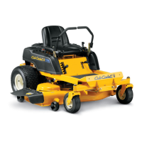
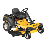
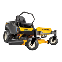
Brakes and Drive System
43
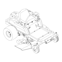
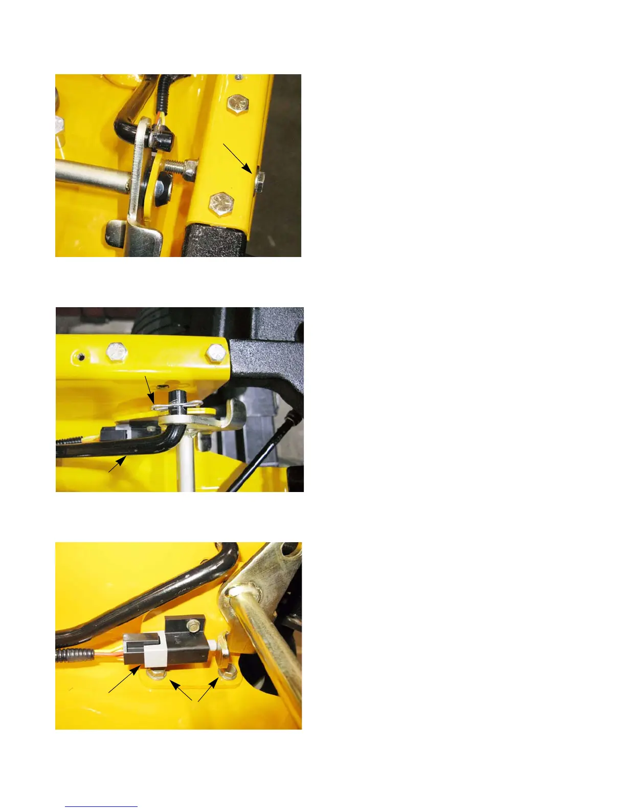
12. Remove the bolt that is pressing against the left con-
trol pedal shaft bracket and its nut using a pair of 9/
16” wrenches. See Figure 4.43.
NOTE: This bolt is used to limit the side to side movement
of the control pedal shaft assembly. If the mowers
was built prior to March 22, 2012 or has a shorter
bolt that does not press against the control pedal
bracket, replace it with a 3/8-16 x 2.50” grade 5
bolt (710-0859). See Service Advisory CC-749.
13. Remove the bowtie clip and disconnect the main
brake rod. See Figure 4.44.
14. Remove the reverse switch. See Figure 4.45.
15. Remove the two screws that hold the left control
pedal bracket to the frame using a 1/2” wrench.
Figure 4.43
Bolt
Figure 4.44
Main brake rod
Bowtie clip
Figure 4.45
Reverse switch
Screws
www.mymowerparts.com
For Discount Cub Cadet Parts Call 606-678-9623 or 606-561-4983
 Loading...