29
0306 / 13 013 497A
Installation
Assembly
Assembly
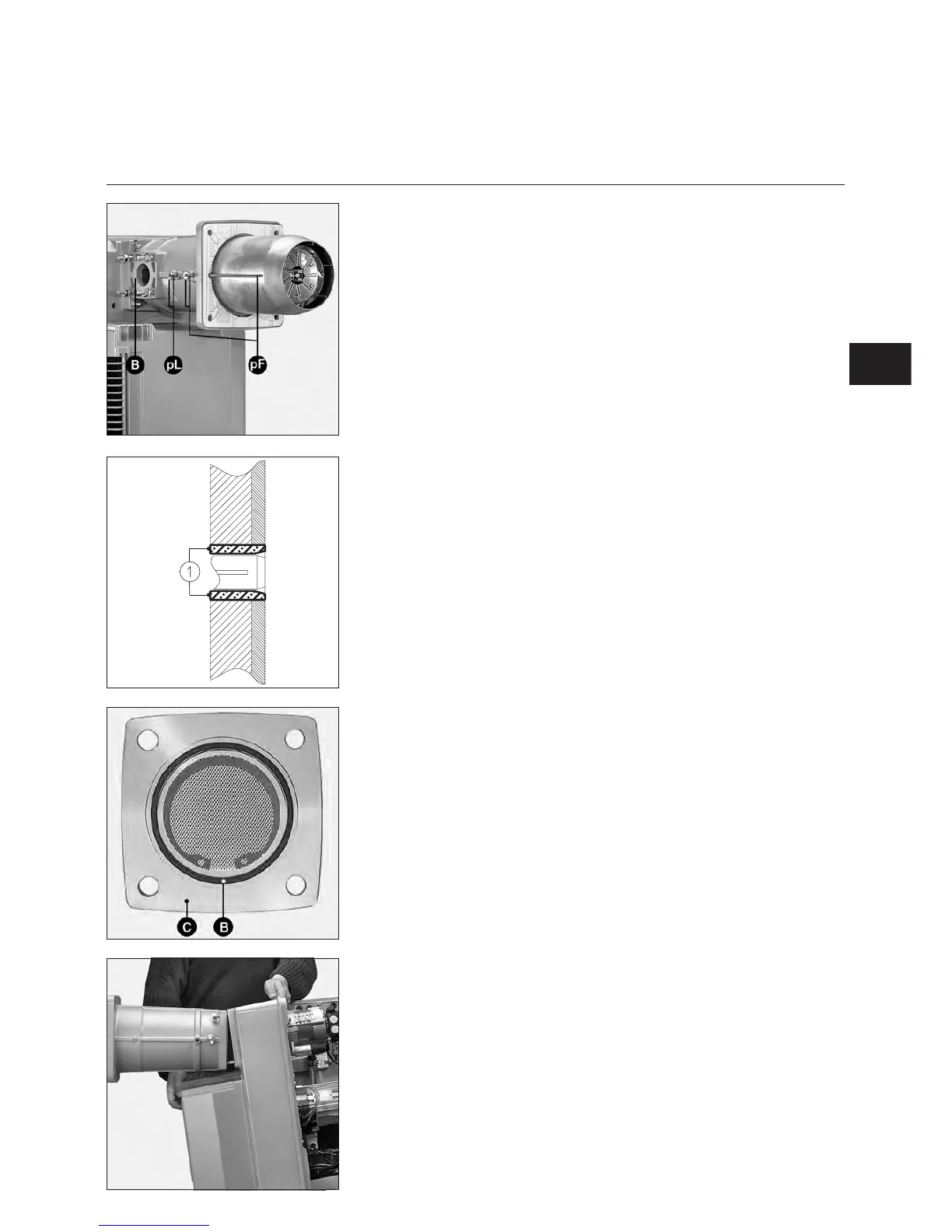
Boiler face
•
Prepare face according to the
enclosed space requirement
diagram.If required, insert a counter
face plate (option).
Pierce: Ø 195 (or Ø 172 with an
opening on the same side as the
gas supply for the tube of the
furnace pressure connector).
•
Fill in space 1 with recommended
heat-resistant material or material
supplied by the boiler manufacturer.
m
Do not obstruct combustion
chamber pressure take-off pF.
Combustion head
•
Remove the combustion
components, store them on standby
in an area sheltered from impacts.
•
Position the combustion head in
order to produce a horizontal
connection with the gas train, on the
right or on the left. No other
assembly positions are
authorised.
• Mount and fix combustion head with
its seal on front of burner.
• Check subsequently for leaks.
Gas manifold
• Check presence and position of
O-ring B in manifold C flange.
• When fitting gas manifold, valve
coils must be in the vertical top
position.
Important
When using a left-mounted VGD gas
train, it is necessary to pivot the SKP70
regulator 180°.
To do this:
•
Remove the SKP70 regulator.
•
Remove the connector (3P+T) on
the side of the regulator and
remount it opposite.
m
Seal off the old position of the
connector.
•
Refit the regulator once it has been
pivoted a half turn (180°).
Burner body
Installation can occur with the volute
low down or high up following the
instructions described in the paragraph
“combustion components start-up”.
No other assembly positions are
authorised.
Volute low down :
•
Remove the two lower nuts and
unscrew as far as possible the two
upper nuts from the body of the
burner.
•
Lean the body of the burner forward,
and insert the upper studs into the
slots in the spacer.
•
Rest the burner body on the spacer
and tighten the four nuts.
Volute high up : reverse previous
instructions.
EN
•
Place the linking tubes of the
combustion components (stored on
stand-by) on the pump without pulling
them too tight or gripping them too
hard.