38
0306 / 13 013 497A
Start-up
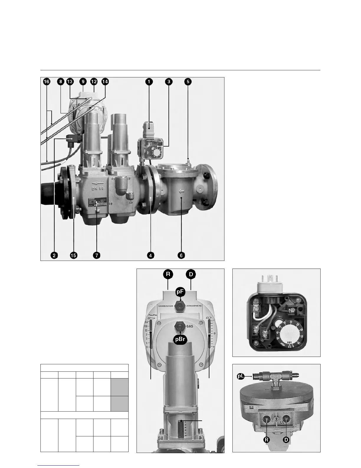
Description and settings
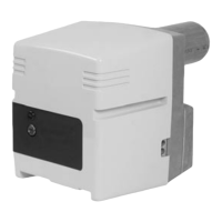
VGD gas valve
SKP70 regulator
1 Pressure switch electrical
connection (DIN 43650)
2 Solenoid electrical connection
(DIN 43650)
3 Pressure switch
4 Intake flange
5 Pressure take-off G 1/8 before
the filter
6 External filter DN65
7 Identification plate
8 Air pressure pL G 1/8 connection
9 Adjusting screw R of gas flow/air
flow ratio
12 Adjusting screw D for correcting
zero point
13 Connection G 1/8 for combustion
chamber pressure pF
14 Connection G 1/8 for gas
pressure pBr
15 Outlet flange
16 pBr - pL - pF pressure take-off
pipes
The VGD valve associated with SKP70
regulator ensures a constant gas
flow/air flow ratio and is quick-acting.
The regulator also takes into account
combustion chamber pF pressure.
The valve is delivered preset according
to table here below.
Setting gas pressure switch
• Remove transparent cover.
Unit includes a ↑|↓index and
graduated mobile disk.
• Provisionally set pressure switch to
the minimum value shown on
graduated disk.
R ratio
indicator
D value
indicator
Gas valve
openig
indicator
Burner C75 B 517/8
Gas P VGD 20.507 40.065
G20 20
d
(Vis R)
2
d
(Vis D)
1,4
Burner C100 B 517/8
G20 20
d
(Vis R)
22
d
(Vis D)
1,4 1,3