37
0306 / 13 013 497A
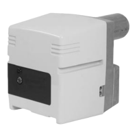
NV
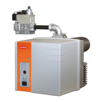
Setting regulator
All settings are performed with burner
on.
•
Set using a 2.5mm hex key/spider
wrench on two screws marked 9
and 12.
–
Screw V provides gas/air ratio;
graduated 0.75 to 3.0
–
Screw N allows adjustment of
excess air to minimal flow;
graduated -2 to +2.
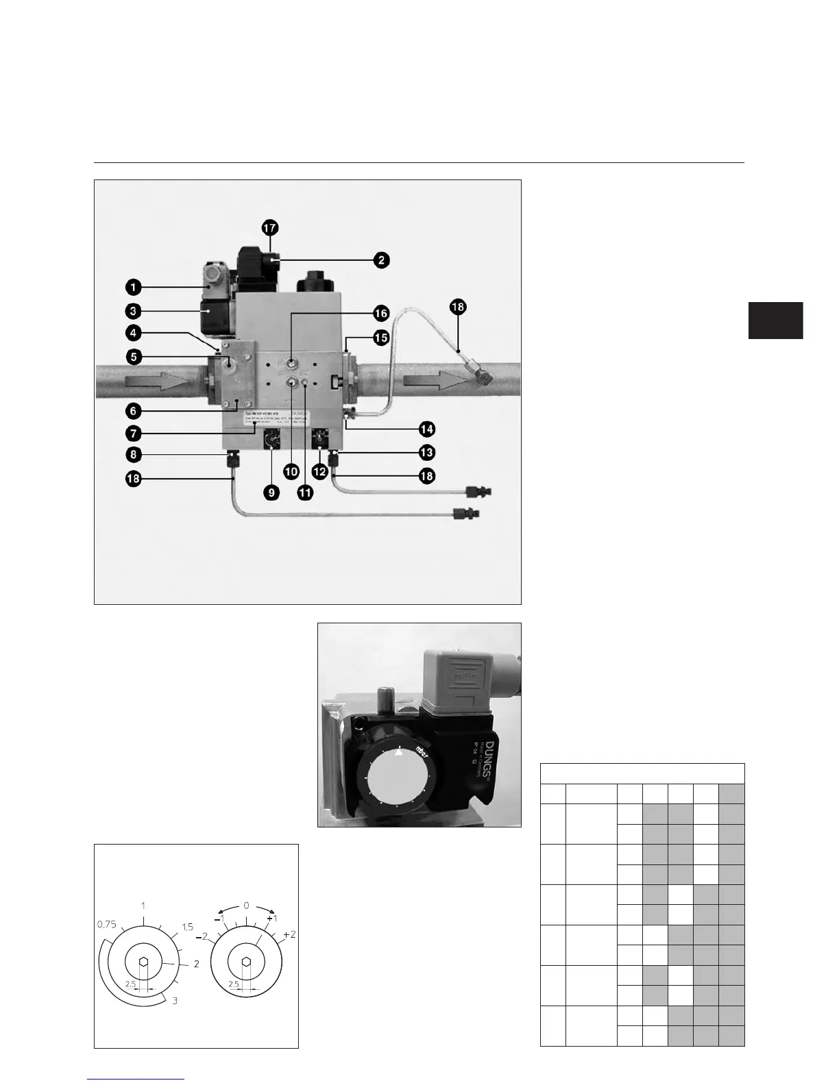
1 Pressure switch electrical
connection (DIN 43650)
2 Solenoid electrical connection
(DIN 43650)
3 Pressure switch
4 Intake flange
5 Pressure take-off G 1/8 before
possible filter on either side
6 Filter under cover
7 Identification plate
8 Air pressure pL G 1/8 connection
9 V ratio adjusting screw
10 Pressure take-off pe G 1/8 both
sides
11 Gas pressure take-off pBr M4
(V2)
12 Adjusting screw for correcting
zero point N
13 Connection G 1/8 for combustion
chamber pressure pF
14 Connection G 1/8 for gas
pressure pBr
15 Outlet flange
16 Pressure pa take-off after V1 both
sides
17 On indicator V1, V2 (optional)
18 pBr - pL - pF pressure take-off
pipes
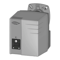
Setting gas pressure switch
•
Remove transparent cover. Unit
includes a x index and graduated
mobile disk.
•
Provisionally set pressure switch to
the minimum value shown on
graduated disk.
Start up
Description Settings
Gas valve
MB VEF valve
MB VEF valve … is a compact assembly
including the following:
A screen, adjustable pressure switch,
non-adjustable quick-acting safety
valve, proportional regulator-controlled
main valve which can be adjusted on
opening (V and N). It ensures a
constant gas flow/air flow ratio and is
quick-acting. The regulator also takes
into account combustion chamber pF
pressure.
The valve is delivered preset according
to table here below.
EN
Burners C 75/100 B 517/8
Gas p
VEF
407 412 420 425
G20
20-25
40-50
V
1,25
N
0
G25 25
V
1,25
N
0
G20 50-100
V
1,35
N
-0,5
G20 300
V
1,5
N
0,5
G31 30-37-50
V
1,35
N
-0,5
G31 148
V
1,5
N
0,5