45
0306 / 13 013 497A
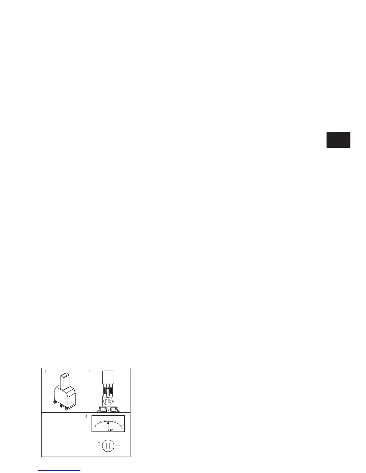
GAS working cycle test
FUEL OIL valves must be closed
•
Open, then immediately reclose fuel
quarter-turn hand-operated valve.
•
Switch burner on.
•
Select, on burner control panel TC,
gas manual operating mode
S1/H10.1 - S29J -S2K -S4.
•
Close thermostatic circuit.
•
Open the control and safety unit and
check if it is working correctly.
Program sequence should be as
follows:
–
complete opening of the air flap,
–
preventilation for 30s,
–
return to ignition position,
–
electrodes ignition for 6s,
–
valves open,
–
valves close no more than 3s after
opening,
–
burner stops due lack of gas
pressure or control and safety unit
locks because flame goes out.
If a doubt arises, repeat the above
test.
Unit can only be fired once this very
important working cycle test has been
performed.
Firing
m
Warning:
Unit may be only fired when all
the requirements listed in
previous sections have been met.
Notably, choice of priority fuel
(fuel oil).
•
Connect a microammeter (0-500µA
DC scale) instead of measuring
bridge found under TC.
m
Respect the direction of
connection.
•
Close FUEL OIL valves.
•
Open GAS valves.
•
Close thermostatic circuit.
•
Release control and safety unit.
Burner is in operation.
•
Check the following :
–
combustion as soon as flame
appears,
–
any possible gas manifold leaks.
No leaks should be observed.
• Read cell current (value set from
200 to 500µA).
• Measure gas flow at meter.
• Increase power to nominal flow-rate
by pressing S3+ pulse switch.
• Check combustion.
Comply with recommended boiler
manufacturer smoke temperature
value, in order to obtain the required
effective output.
According to combustion value, with
burner working at nominal rate, turn
screw V on valve MB VEF, or screw R
of SKP regulator.
•
To increase CO
2
rate, increase the
ratio and vice versa.
•
Read cell current (value set from
200 to 500µA).
•
Measure gas flow at meter.
•
Increase or reduce power by
increasing or reducing value read on
cam I graduated cylinder.
•
Stop, then restart burner.
•
Check combustion as soon as flame
appears.
According to measured values, with
burner in operation, turn screw N on
valve MB VEF, or screw D of SKP
regulator.
•
If required, adjust cam III value.
•
Increase power to min. regulation
flow.
•
Check combustion.
•
Adjust air/gas flow via cam V for
min. regulation. Setting is performed
in the same way as for cam I.
•
Return power to nominal flow and
check combustion parameters. If
value has changed after turning
screw N (screw D for SKP), adjust
ratio V (screw R for SKP) as
appropriate.
m
Important: do not reset
dimension Y, if FUEL OIL has
been set, otherwise :
•
Optimize combustion results by
adjusting dimension Y secondary
air, according to procedure
described in the “ Setting
combustion and secondary air
components ” section.
•
Reduce dimension Y,CO
2
index
increases and vice versa.
Any dimension Y modification may
require adjusting secondary air.
•
Check combustion.
Check operation during the following:
firing, increasing and decreasing
power.
•
While burner is in operation and
using foam designed for that
purpose, check for any possible
leaks in gas manifold connections.
No leaks should be observed.
•
Check safety units.
Start up
Working cycle test
Firing gas
EN