31
0306 / 13 013 497A
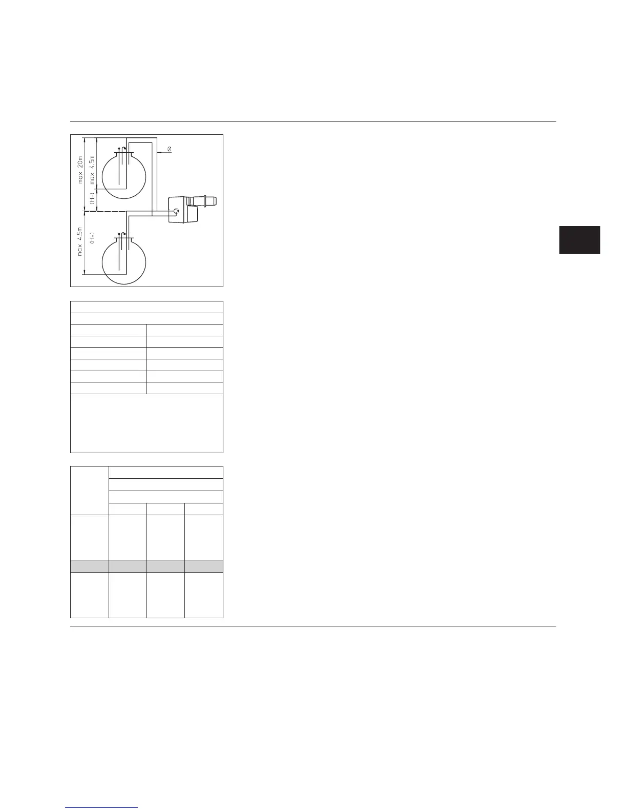
Altitude correction
Suction (H+) or loading (H-) pump
Altitude (m) Dummy H (m)
0-500 0
501-800 0,5
801-1300 1,0
1301-1800 1,5
1801-2200 2,0
e.g. Altitude 1,100m Dummy H=1m Real H=2m
Suction corrected H 2 + 1 = 3m
Load corrected H 2 - 1 = 1m
Choose pipe diameter in table, according to length
between tank and pump.
If suction corrected H exceeds 4m, have transfer pump
available (max. pressure 2 bars).
Corrected
H
(m)
Double tube installation L (m)
C 75 / C 100
Ø (mm)
10/12 12/14 14/16
4,0
3,0
2,0
1,0
+0,5
51
45
38
32
29
83
83
82
69
62
83
83
83
83
83
0 265683
-0,5
-1,0
-2,0
-3,0
-4,0
22
19
13
6
0
49
42
29
16
2
83
80
55
31
6
Fuel oil connection
Enclosed diagrams provide required
pipe diameters.
There are two following possibilities:
–
Direct suction:
According to length L and suction or
load height H and chance mishaps;
These lengths include the presence
of a quarter-turn hand-operated
valve, a check valve and four
elbows.
Maximum negative pressure of
0.4bar.
–
Transfer loop:
According to the type of facility,
booster pump characteristics will
have to meet several criteria,
notably:
–
hourly flow,
–
fluid flow speed,
–
maximum boosting pressure.
Preference should be given to this
type of installation, in order to
obtain long spray pump life.
m
Important
In both cases, it is compulsory to
fit a 120µm² filter and quarter-turn
hand-operated valve on the suction
or booster (not supplied).
Important:
Suction:
•
Totally fill suction pipe between
spray pump and tank down-pipe
with fuel oil.
Transfer loop:
•
Fill, boost, drain and set pressure in
circuit at 2bar max. It is advisable
to install a pressure switch to limit
burner operation to boost pressure.
•
Check for possible leaks.
Installation
Fuel oil connection
EN