EasyManua.ls Logo

CUH SDMC20-S - User Manual

CUH SDMC20-S
48 pages
Print Icon
To Next Page IconTo Next Page
Loading...
CUH CUH CUH CUH CUH CUH CUH
CUH CUH CUH CUH CUH CUH CUH CUH CUH CUH CUH CUH CUH CUH CUH CUH CUH CUH CUH CUH CUH
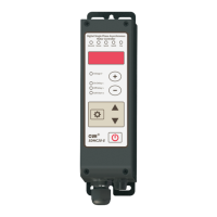
Digital Single Phase Asynchronous Motor Controller
SDMC20-S
User Manual

Questions and Answers

CUH SDMC20-S Specifications

General IconGeneral
CategoryController
Motion SensorSix-axis motion sensing system (three-axis gyroscope, three-axis accelerometer)
Light BarYes
SpeakerBuilt-in mono speaker
ModelSDMC20-S
ConnectionBluetooth, USB
BatteryLithium-Ion Rechargeable Battery
ButtonsDirectional buttons, Action buttons (Triangle, Circle, Cross, Square), Shoulder buttons (R1/L1), Triggers (R2/L2), Options button, PS button, Touch Pad button
Touch PadYes
VibrationYes
Headset Jack3.5mm
Compatible PlatformPlayStation 4

Summary

Copyright Statement

Disclaimer

Preface

Safety and Precautions

Operating and Storage Environment

Inspection Before Using

Verify the controller and accessories are intact upon receipt. Contact the company if any issues are found.

Runtime Environment

Notes for ensuring better performance and longer lifetime, focusing on ventilation and environmental conditions.

Chapter I Before Use

Check the Package Contents

Verify the controller and accessories are intact upon receipt. Contact the company if any issues are found.

Indicators, Buttons and External Parts Explanation

Wiring Ports Explanation

Nameplate Explanation

Chapter II Featured Functions

Product Introduction

Overview of the SDMC20-S controller's capabilities, including soft start, speed stabilization, and protection functions.

Chapter III Installation Guide

Controller Usage Conditions

Specifies the necessary environmental and electrical conditions for safe and proper controller installation and operation.

Operation Method of Buttons

Details how to use the controller's buttons in both modern and traditional parameter interfaces.

Install and Use

Chapter IV Basic Function Description

Output Voltage (Speed) Setting

Explains how to set the output voltage or speed using the controller's interface and buttons.

Soft Startup;Shutdown Time

Output Switch

Keyboard Lock

Restore Default Settings

Chapter V Advanced Function Description

Remote Speed Control

Details how to control the motor speed using external analog signals like potentiometers or voltage/current inputs.

Intelligent Photoelectric Sensing

Explains the connection and configuration of intelligent photoelectric sensors for detection purposes.

Switch Sensor

Describes the support for NPN, PNP, Ut1, and Ut0 modes for switch sensor connections.

Wiring Method of Control Output

Illustrates the wiring configurations for NPN and PNP/push-pull output types for control signals.

Control Output Signal Source and Logic Diagram

Explains the available signal sources and logic diagrams for controlling the main and control outputs.

Control Output Mode Description

Describes the two control output modes: delay mode and hold mode, with timing diagrams.

Main Output Signal Control Function

Explains how the main output signal is controlled, similar to control output, using logic operations and on/off signals.

Speeds Preset Function

Details how to use external control signals to select preset motor speeds for multi-speed control systems.

Motor Forward and Reverse Adjustment

Provides instructions on how to change the motor's rotation direction by adjusting the output connector position.

Motor Stall Protection

Explains the motor stall protection feature, how it triggers (Err22), and how to resume operation.

Parameter Monitoring Function

Describes how to view various operating parameters for monitoring and debugging purposes.

Parameter Password Lock Function

Details how to lock key parameters using a password to prevent misoperation and unauthorized changes.

Control Vibratory Feeder Mode

Explains how to connect the controller to a vibratory feeder and set it for feeder control mode.

Set to SDVC21-S Interface

Instructions on how to restore factory settings to use the traditional SDVC21-S interface for feeder control.

Chapter VII Appendix

Parameter Table

A comprehensive table listing all controller parameters, their symbols, ranges, and default values.

Input and Output Circuit Diagrams

Diagrams illustrating the electrical connections for various input and output ports of the controller.

Troubleshooting Suggestions and Error Explanations

Provides common error codes and their corresponding troubleshooting methods for diagnosing issues.

Chapter VI Technical Specifications

Dimensions

Provides detailed physical dimensions of the controller unit in millimeters.

Technical Specifications

Lists the electrical and performance specifications of the controller, including voltage, current, and frequency.

Reference Standard

Details the GB and IEC standards the controller complies with for electrostatic discharge and immunity.

Chapter VIII Product Warranty Information

Warranty Period

Specifies the warranty duration for the product, which is 3 years from the date of delivery.

Warranty Coverage

Outlines the conditions and exclusions for product warranty coverage.

Product Suitability

Defines the intended applications and industries for the controller and those it is not suitable for.

Related product manuals