D
David MccannSep 13, 2025
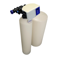
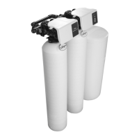
What to do if there is mineral to service in my Culligan High Efficiency 1.5 Water Dispenser?
- BBrittany AtkinsonSep 13, 2025
If you find mineral in the service line of your Culligan Water Dispenser, the outlet manifold may be defective and require replacement.