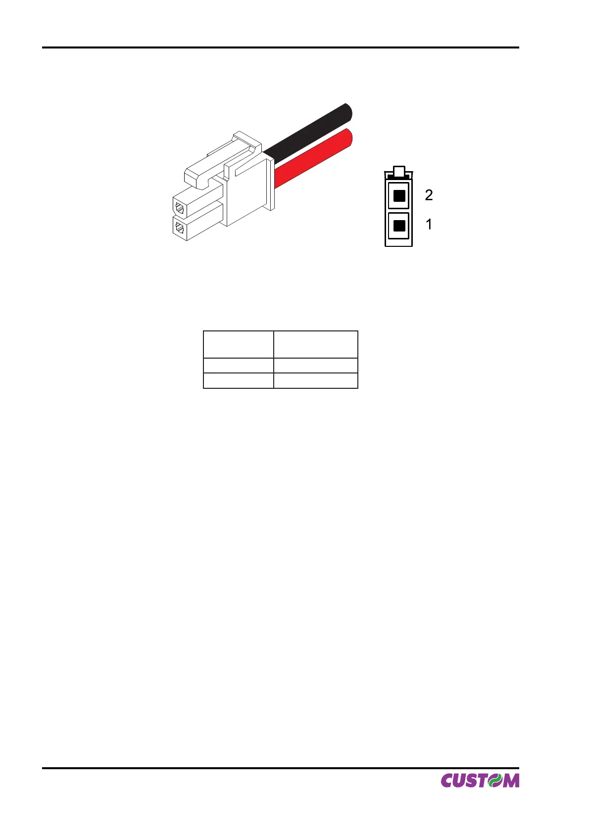
This picture shows the power supply cable included in the printer packaging :
The connector pin confi guration of this cable is as follows:
Female
connector
Cable color
Pin 1 RED
Pin 2 BLACK
Note : The red cable is for +24 Vdc.
The black cable is for signal ground.
1.2 SELF-TEST
Printer operating status is indicated in the confi guration print-out in which, next to the name of the compo-
nents displayed (see fi gure 1.3), the following information is given:
Under INTERFACE is given the interface present (RS232).•
Under PROGRAM MEMORY TEST, DYNAMIC RAM TEST, EEPROM TEST and CUTTER TEST, the •
message OK appears if functioning and NOT OK if faulty.
Under HEAD VOLTAGE is given the voltage of the head.•
Under HEAD TEMPERATURE is given the temperature of the head. •
Under PAPER PRINTED is given the number of centimetres of paper printed. •
Under CUT COUNTER is given the number of cuts made. •
Under RETRACT COUNTER is given the number of retract made. •
Under POWER ON COUNTER is given the number of power-ups made.•
(Fig.1.2)
MOLEX FEMALE
CONNETTOR 2 PIN
OPPOSITE VIEW SIDE
OF CABLE INSERTION
(Tab.1.2)
1. INSTALLATION AND USE
1-2 VKP80II User Manual