Do you have a question about the Custom Engineering PLUS II and is the answer not in the manual?
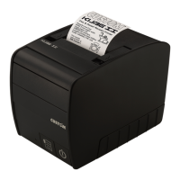
Identifies and labels the physical components visible on the front of the PLUS II printer.
Details the rear panel connectors and interface options for various PLUS II printer models.
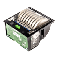
Illustrates and labels the internal parts and sensors of the PLUS II printer.
Outlines the organization and content of the PLUS II user manual.
Explains the meaning of symbols like N.B., WARNING, and DANGER used in the manual.
Provides critical safety precautions for operating and handling the PLUS II printer.
Step-by-step instructions for safely removing the printer from its packaging.
Highlights the main features, capabilities, and applications of the PLUS II printer.
Describes the ABS casing, front cover, and control panel elements of the PLUS II.
Explains the functions of the FEED key for paper advancement and entering setup mode.
Details how to use the OPEN key to open the paper roll compartment.
Interprets the colors and flashing patterns of the status LED for printer diagnostics.
Outlines the requirements and specifications for thermal and LINERLESS paper.
Provides specific dimensions and properties for LINERLESS thermal paper.
Details the specifications for label roll paper, including notch alignment.
Describes the serial RS232/TTL interface and power supply connector for these models.
Details the pin configuration and signal assignments for the power supply connector.
Explains how to configure the serial interface using JP4, JP5, JP6, and JP7 jumpers.
Details the RS232 interface and power supply connection for the PLUS II-S-0004 model.
Details the pin configuration and signal assignments for the power supply connector.
Refers to section 1.2.2 for serial interface setting details.
Explains the JP8 jumper for managing auto power-on and low-consumption modes.
Details the parallel Centronics/TTL interface and power supply connector for these models.
Details the pin configuration and signal assignments for the power supply connector.
Explains how to configure the parallel interface using JP1 and JP2 jumpers.
Details the parallel Centronics interface and power supply connection for the PLUS II-C-0004 model.
Details the pin configuration and signal assignments for the power supply connector.
Refers to section 1.4.2 for serial interface setting details.
Explains JP5 and JP6 jumper settings for parallel interface signals.
Details the USB interface and power supply connection for the PLUS II-USB model.
Details the pin configuration and signal assignments for the power supply connector.
Explains how to interpret printer status and configuration from the self-test report.
Lists configurable default parameters for various PLUS II models and their options.
Describes the function to view received data as hexadecimal and ASCII codes.
Introduces the maintenance procedures section of the manual.
Step-by-step instructions for changing the paper roll in the printer.
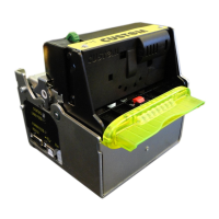
Provides guidance on physically mounting the printer to a panel or surface.
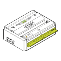
Explains the operation of the EASYLOCK system for secure panel installation and removal.
Details the 6-pin Molex connector and signals for the RS232/TTL interface.
Shows the wiring diagram and pinout for connecting the printer to a PC via serial cable.
Explains the transmission format and signaling for RTS/CTS and XON/XOFF protocols.
Illustrates the signal timing diagrams for the XON/XOFF communication protocol.
Details the 6-pin AMP-MODU II connector and signals for the RS232 interface.
Shows the wiring diagram for connecting the printer to a PC via RS232.
Provides a detailed pin-to-pin wiring scheme for the RS232 interface connection.
Details the 15-pin Molex connector and signals for the Centronics/TTL interface.
Shows the connection cable configuration for parallel interface to a PC.
Provides a detailed wiring scheme for parallel interface connection between printer and PC.
Explains the communication signals (DATA BUS, STROBE, BUSY) and flow for TTL interface.
Details the 15-pin Molex connector and signals for the Centronics interface.
Shows the connection cable configuration for parallel interface to a PC.
Provides a detailed wiring scheme for parallel interface connection between printer and PC.
Details the 6-pin AMP-MODU II connector and signals for the USB interface.
Explains the pinout and signal assignments for the USB connector.
Notes that the RS232 serial interface on this model is reserved for service use only.
Presents a comprehensive table of the printer's main technical specifications.
Details print resolution, mode, format, and character matrix for specific models.
Details print resolution, mode, format, and character density for the USB model.
Lists power supply voltages and current absorptions for various non-USB models.
Lists power supply voltage and current absorptions for the USB model.
Shows diagrams illustrating the external dimensions of the PLUS II printer.
Illustrates the physical dimensions of the PLUS II printer with the OPTION -0128.
Introduces the concept of fonts and character sets available for the PLUS II printers.
Displays an example of Font 1 character set for specific PLUS II models.
Lists and illustrates the code tables and character sets supported by the PLUS II-USB.
Lists optional accessories that can be purchased for the PLUS II printer.
Details the technical specifications of the 5V 25W switching power supply accessory.
Details the technical specifications of the 24V 100W switching power supply accessory.
Describes the adaptor frame kit used for mechanical compatibility with other printer series.
Provides step-by-step instructions for assembling the printer with the adaptor frame.
Illustrates the overall dimensions when the printer is mounted with the adaptor frame.
Details the starter kit containing power and serial data cables for specific models.
Describes the data serial cable kit included for the PLUS II-S-0004 model.
Details the starter kit containing power and parallel data cables for specific models.
Describes the data parallel cable kit included for the PLUS II-C-0004 model.
Introduces the section detailing spare parts and consumables for the printer.
Lists recommended paper rolls (thermal, linerless, label) and quantities.
| Brand | Custom Engineering |
|---|---|
| Model | PLUS II |
| Category | Printer |
| Language | English |