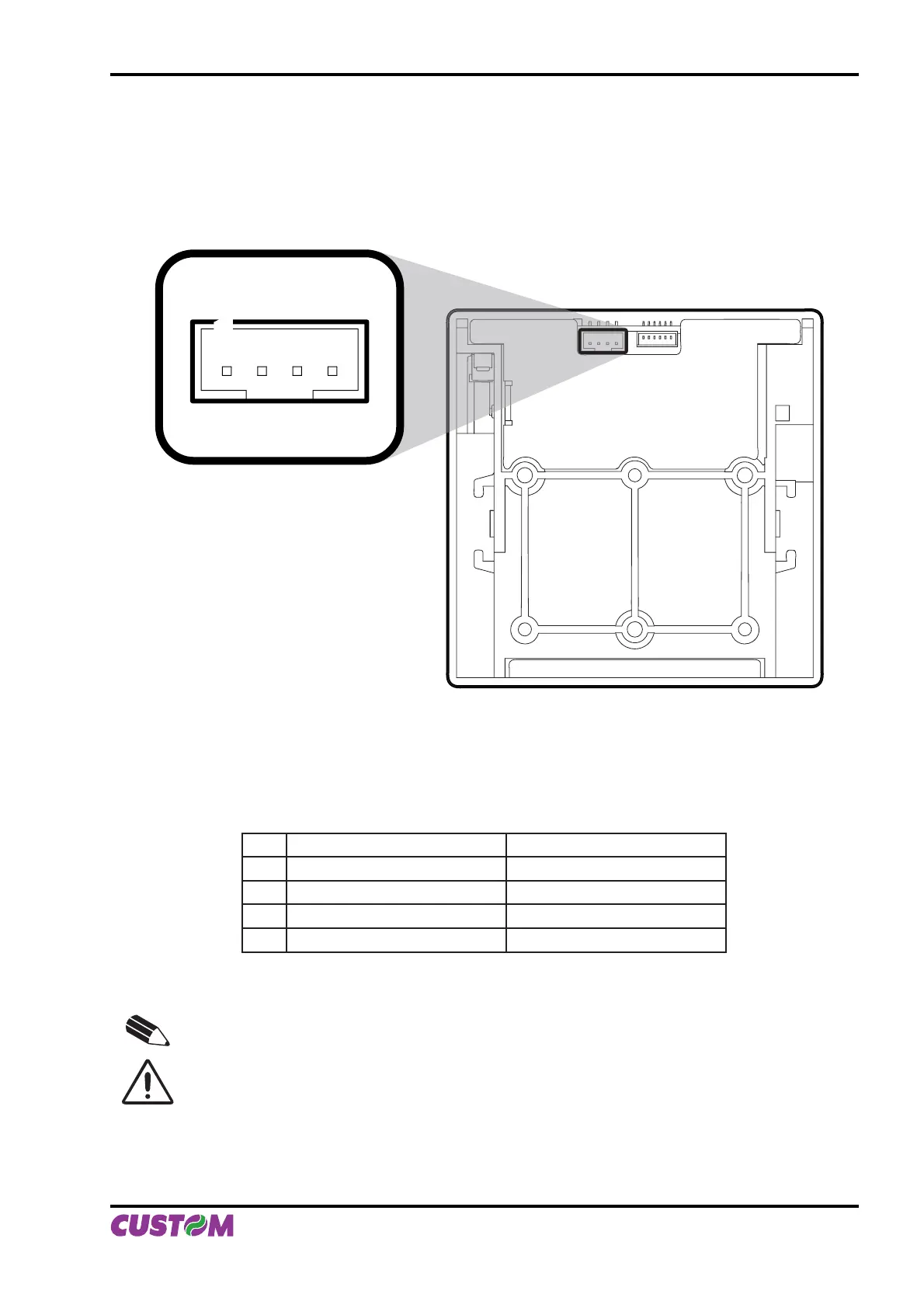
1.2 CONNECTIONS OF PLUS II-S AND PLUS II-T
1.2.1 Power supply
The printer is equipped with a 4 pin JST male connector (90°) for the power supply. The signals on the con-
nector pins are as follows:
1
Model no. type:
Header: S4B-PH-K-S 90° (JST)
Housing: PHR-4 (JST) or equivalent
PIN SIGNAL DESCRIPTION
1 GND Ground signal
2 GND Ground signal
3 +Vin* Head voltage
4 +Vcc* Logic supply voltage
NOTE
(*) For the electrical specifi cations see Chapter 3.
WARNING
Respect the polarity of the power supply.
(Fig.1.3)
1. INSTALLATION AND USE
User Manual PLUS II 1-3