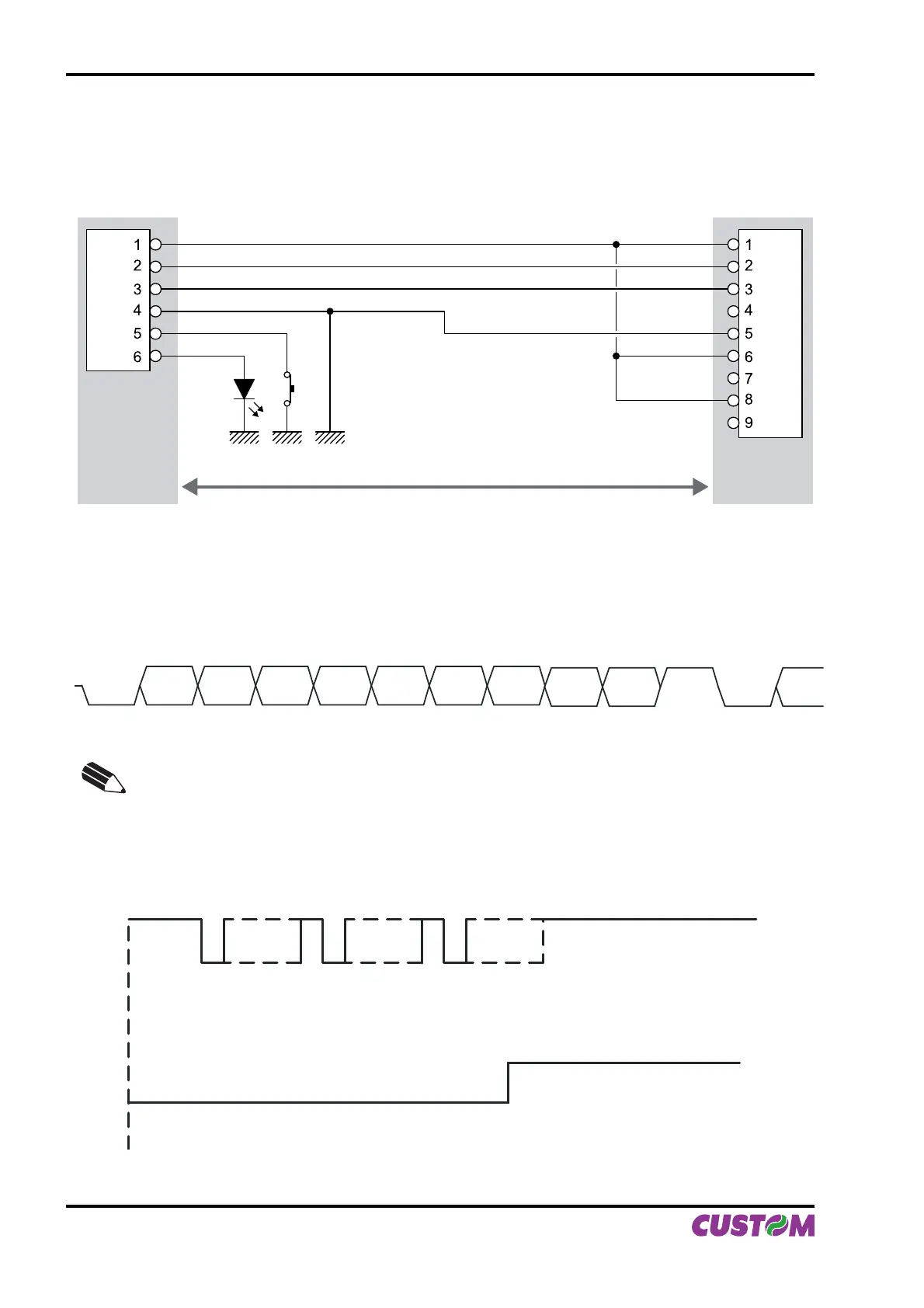
2.1.1 Connection Printer-PC
The diagrams below show a sample connection between printer and Personal Computer using a 6 pin female
Molex 51021 connector by printer side and a 9 pin female connector by a PC side.
Printer PC
DTR DTR
RX
TX
GND
TX
RX
GND
FEED
LED
1
2
In the serial protocol, the signals which distinguish the communication are TD, RD, and RTS if the RTS/CTS
protocol has been selected while, if the XON/XOFF protocol has been selected, the signals are TD and RD.
Transmission format
BIT 0
START
BIT
BIT 1 BIT 2 BIT 3 BIT 4 BIT 5 BIT 6
BIT 7
(1)
PARITY
BIT
(2)
STOP
BIT
NEXT
START
BIT
NOTE
(1)
Bit 7 is present if only in the printer set-up is enabled 8 bit/char as data length.
(2)
Parity Bit is preset if only in the printer set-up the parity is enabled.
RTS/CTS Protocol
DATARD
RTS
STOP
START START START
STOP STOP
DATA WAITDATA
(Fig.2.2)
2. INTERFACES
2-2 PLUS II User Manual