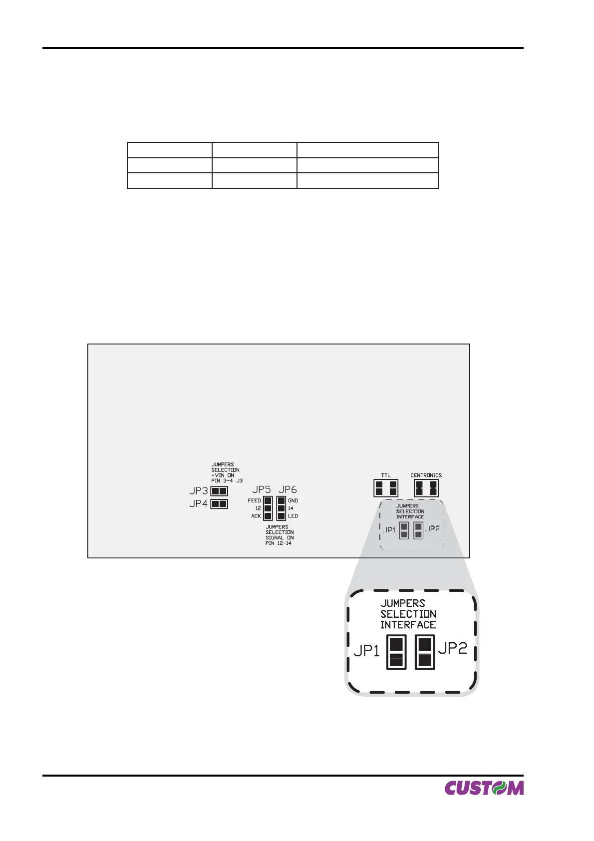
1.4.2 Setting serial interface
The JP2 and JP1 jumpers on controller board (see Fig.1.8) manages the setting of parallel interface as indicated:
JP1 JP2
PARALLEL INTERFACE SELECTION
CLOSED CLOSED Centronics
OPEN OPEN TTL
If JP1 and JP2 are closed:• the Centronics parallel interface is selected.
If JP1 and JP2 are open:• the TTL parallel interface is selected.
Refer to Fig.1.8 for the JP1 and JP2 jumpers position.
JP3
JUMPERS
SELECTION
+VIN ON
PIN 3-4 J3
JUMPERS
SELECTION
SIGNAL ON
PIN 12-14
JP4
JP5 JP6
FEED
12
ACK
GND
14
LED
TTL CENTRONICS
JUMPERS
SELECTION
INTERFACE
JP1
JP2
(Fig.1.8)
1. INSTALLATION AND USE
1-8 PLUS II User Manual