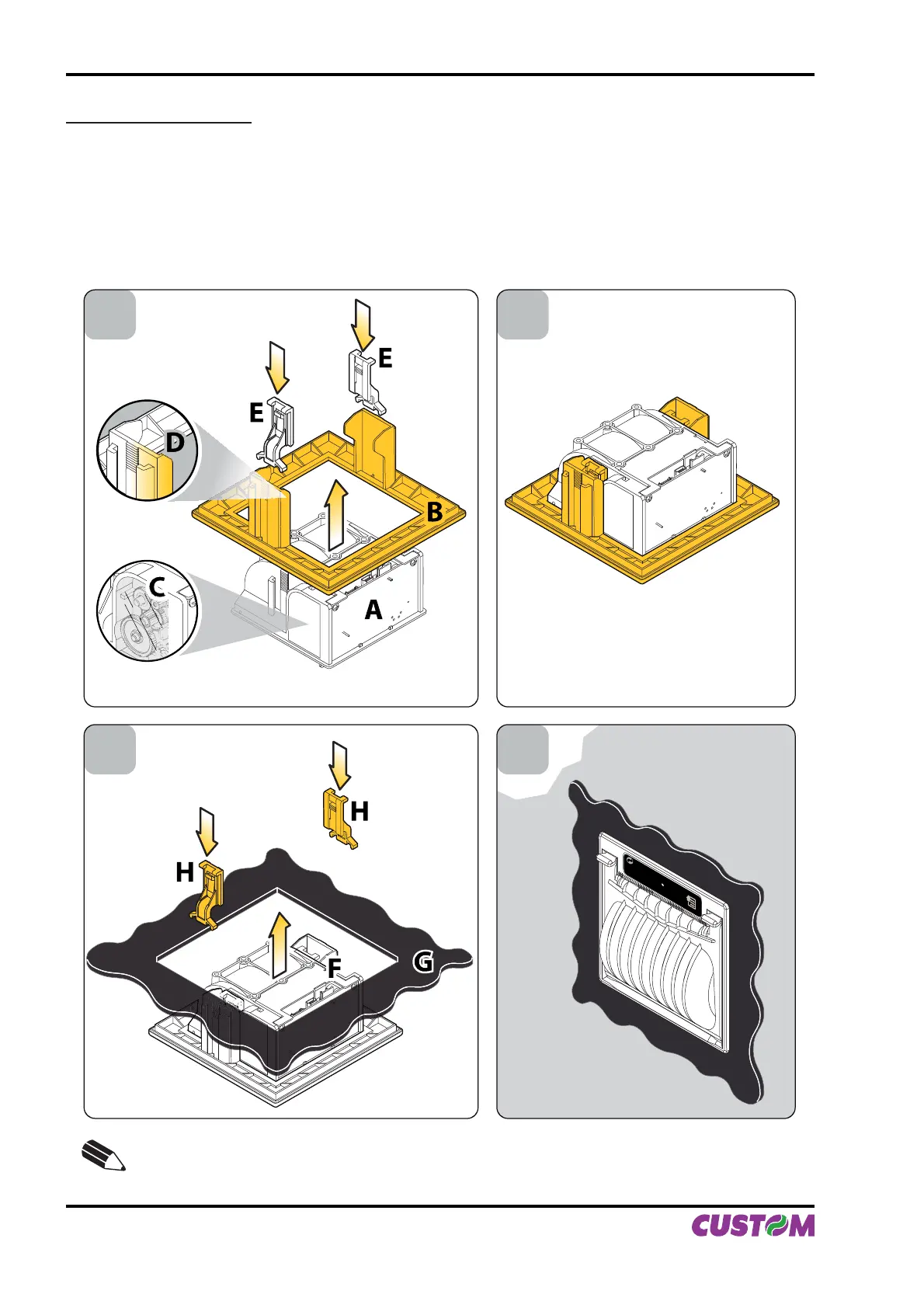
Assembling instructions
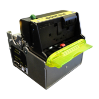
Fit the printer (A) into the adaptor frame (B), making sure that the side of the printer with carter gears (C) •
is aligned with the hooking slide of the frame with the smoothed corner (D), not the side with two hooks.
Fix the printer to the frame using the 2 hooks (E) included with the printer (see fi g.A.4).
The printer/frame unit is assembled (see fi g.A.5).•
Fit the printer/frame unit (F) into the panel (G) and fi x it using the 2 hooks (H), included in the assembling •
kit (see fi g.A.6).
The printer/frame unit is installed on panel (see fi g.A.7).•
1 2
43
E
NOTE:
The mounting operations are valid for all the PLUS II models.
(Fig.A.4) (Fig.A.5)
(Fig.A.6) (Fig.A.7)
APPENDIX A - ACCESSORIES AND SPARE PARTS
A-4 PLUS II User Manual