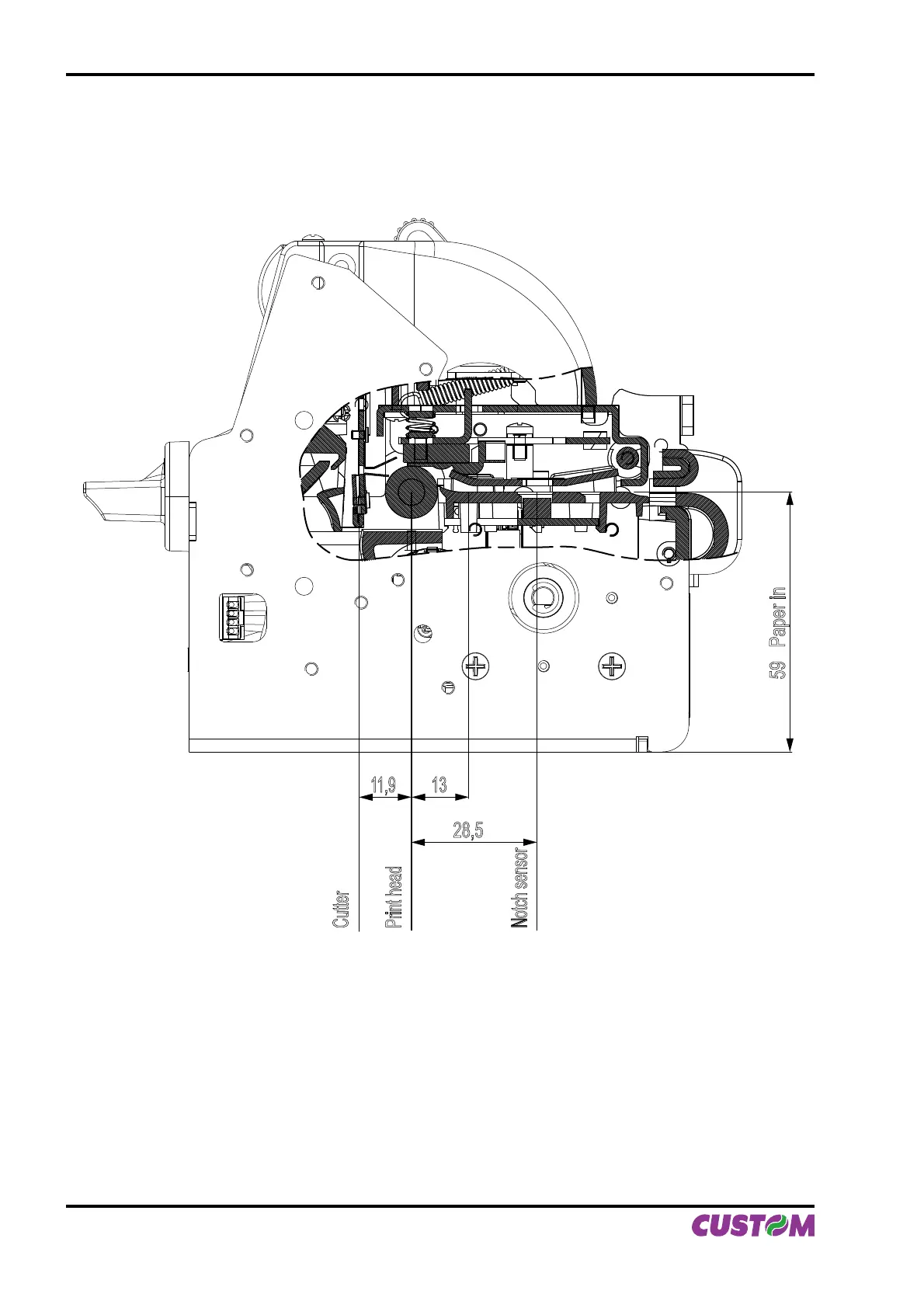
B.3.2 Position of sensors
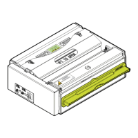
Figure B.11 shows a section of the printer and the distances between the head, the cutter and the notch sen-
sor.
28,5
13
11,9
Cutter
Print head
Notch sensor
59 Paper in
Figure B.11 clearly shows why the alignment distance (Notch Distance) cannot exceed the notch sensor-
head distance. The moment that the notch sensor detects a notch, the head is already mechanically posi-
tioned 32 mm upstream of the of the notch in order therefore for it to align itself with this notch, as a refer-
ence the paper can only be fed forward, and so reduce the distance already there.
(Fig.B.11)
APPENDIX B - ALIGNMENT MANAGEMENT
B-8 VKP80II User Manual