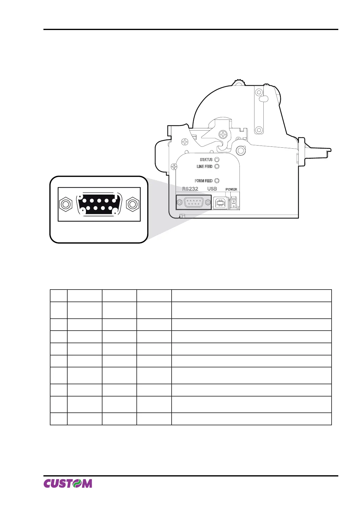
2.1 SERIAL INTERFACE
The printer has an RS232 interface with 9-pin female connector.
RS232
1
5
6
9
Refer to the table below for the connector pin signals:
PIN SIGNAL IN/OUT HOST DESCRIPTION
1 DCD OUT DCD
Individuation Data Carrier.
Printer on (active with RS232 level high)
2 TXD OUT RXD Transmit data. Serial output (from the host)
3 RXD IN TXD Receive data. Serial data input (to the host)
4 N.C. - N.C. Not connected
5 GND - GND Signal Ground
6 DTR OUT DSR
Ready to send.
Printer on and operational (active with RS232 level high)
7 N.C. - N.C. Not connected
8 RTS OUT CTS
Ready to send.
Ready to receive data (active with RS232 level high)
9 N.C. - N.C. Not connected
(Fig.2.1)
(Tab.2.1)
2. INTERFACES
User Manual VKP80II 2-1