Make a note with the connectors position and then disconnect the connectors on the control board.•
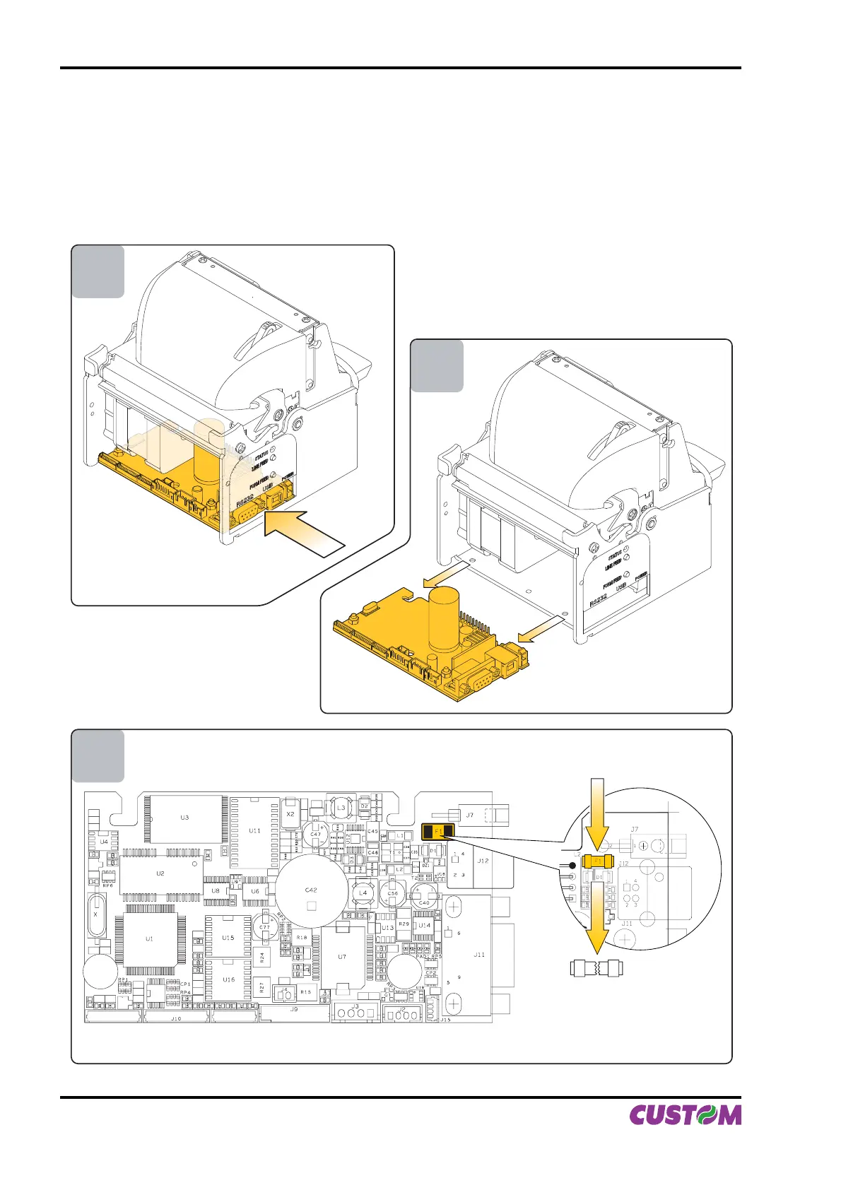
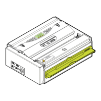
Unlock the control board position pushing in the direction indicated by the arrow as shown in fi g. A.16.•
Extract the control board from its seating in the direction indicated by the arrow as shown in fi g. A.17.•
The fuse is on the control board of the printer, near the supply connector (fi g A.18). Unsolder the fuse at his •
end, paying attention to not heat excessively the closed components, to not take any risk to damage it.
Replace the fuse with a new one with same specifi cations (4A, 125V) and place it again in its seating.•
Reassemble the printer.•
3
4
5
(Fig.A.16)
(Fig.A.18)
(Fig.A.17)
APPENDIX A - ACCESSORIES AND SPARE PARTS
A-10 VKP80II User Manual