PAPER CHARACTERIZATION
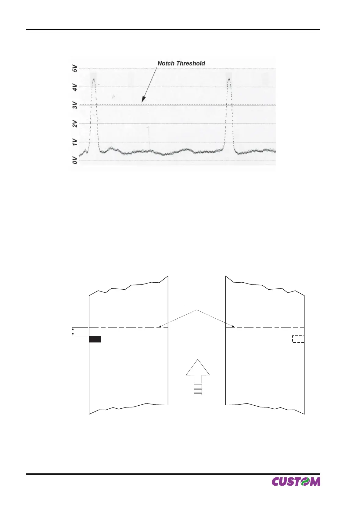
The graphic shows the references in Volts (from 0 to 5V) and the threshold value previously set. It is clear
that by adjusting the threshold value it is possible to fi nd the best position that takes into account the signal
peak and the small oscillations around zero.
The ALIGNMENT POINT is defi ned as the position inside the ticket that is the desired alignment point.
The ALIGNMENT POINT can be defi ned over the notch or near this one; for this reason, the fi nal param-
eters to be set in setup are:
Notch Dist. [mm x 10] . : 1
Notch Dist. [mm x 1] . : 5
These parameters defi ne the “Notch Distance” that represents the distance from the notch to alignent; in the
above example the notch distance is 15 mm.
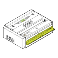
NON HEAT
SENSITIVE Side
Direction of
paper feed
HEAT
SENSITIVE Side
Notch
Distance
Alignment
point
Figure B2 shows how the “Notch Distance” parameter represents the distance that exists between the notch
and the desired alignment point. This parameter can have a minimum value of 0mm (in this case the align-
ments occur in proximity of the beginning of the notch) and a maximum of 32 mm. In reality the maximum
distance corresponds to the mechanical distance between the notch sensor and the head, and it is for this
reason that higher values are not permitted, and negative values are not envisaged.
(Fig.B.2)
(Fig.B.1)
APPENDIX B - ALIGNMENT MANAGEMENT
B-2 VKP80II User Manual