Cybex 750T Treadmill Owner’s Manual
Assembly
and
Setup
Page 2-6
D. Repeat steps 7A to 7C for the right upright.
E. Using a 1/2” box end wrench, fully tighten the two bolts, 5/16-18 x 2.25”, HXHD (#22) and four
nuts (#24) securing the console assembly to the uprights. See Figure 4.
F. Using a 9/16” Socket wrench, fully tighten the ten bolts, 3/8-16 x .625” (#20) securing the uprights
to the base assembly (#1). See Figure 3.
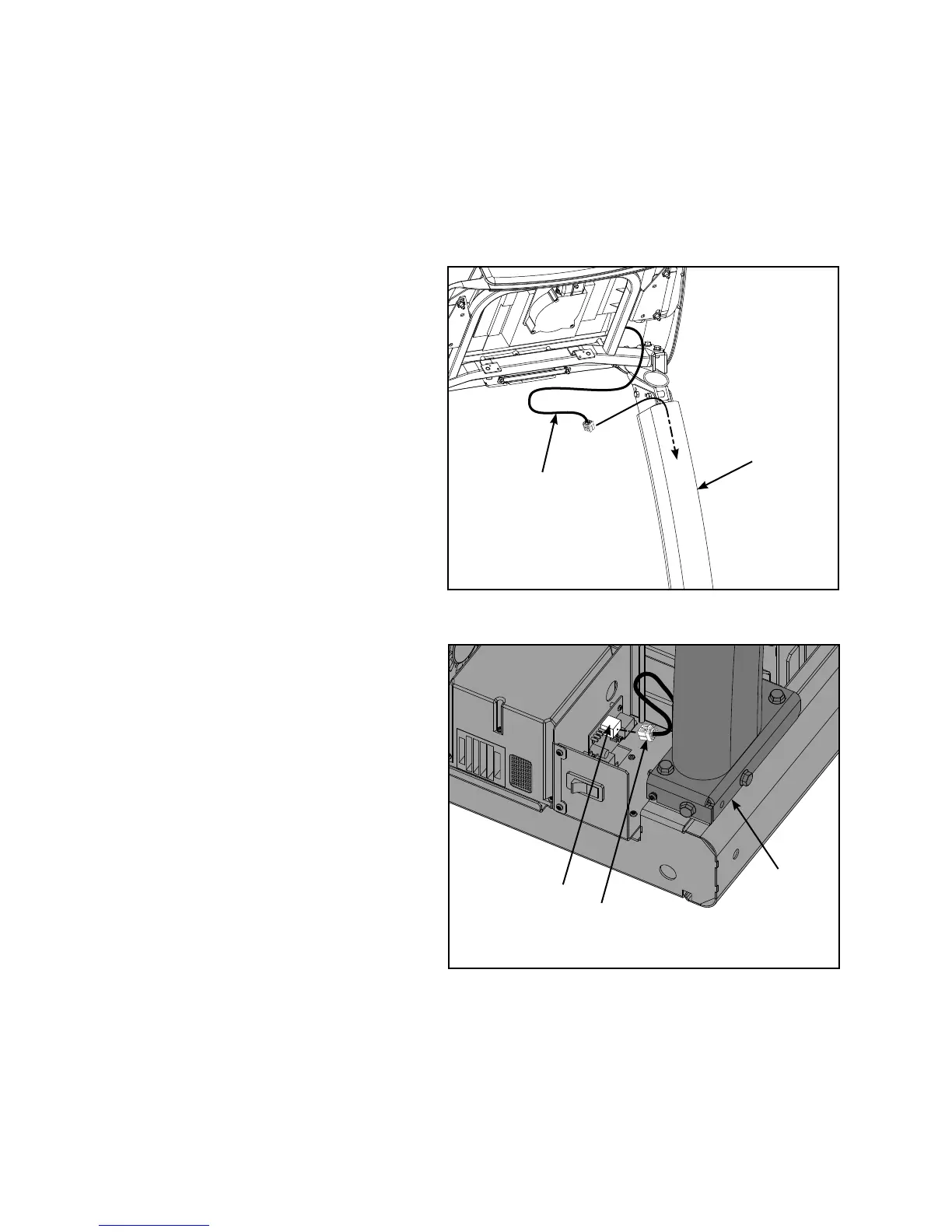
8. Install the Display Cable.
NOTE: Do not pinch or damage display cable
when installing.
Locate the display cable exiting the A.
back of the console assembly.
Insert the display cable into the top of B.
the left upright (#3) until it exits at the
base of the upright (#3). See Figures
5 and 6.
Plug the display cable, located at the C.
bottom of the upright assembly (#3)
into the hub board connector J3. See
Figure 6.
NOTE: If installing the A/V option, refer to
the 750T A/V bracket installation
instructions (supplied with the A/V
bracket).
#3
Figure 5
Display
Cable
Figure 6
Display
Cable
#3
Hub Board
Connector J3
 Loading...