Cybex 750T Treadmill Owner’s Manual
Assembly
and
Setup
Page 2-7
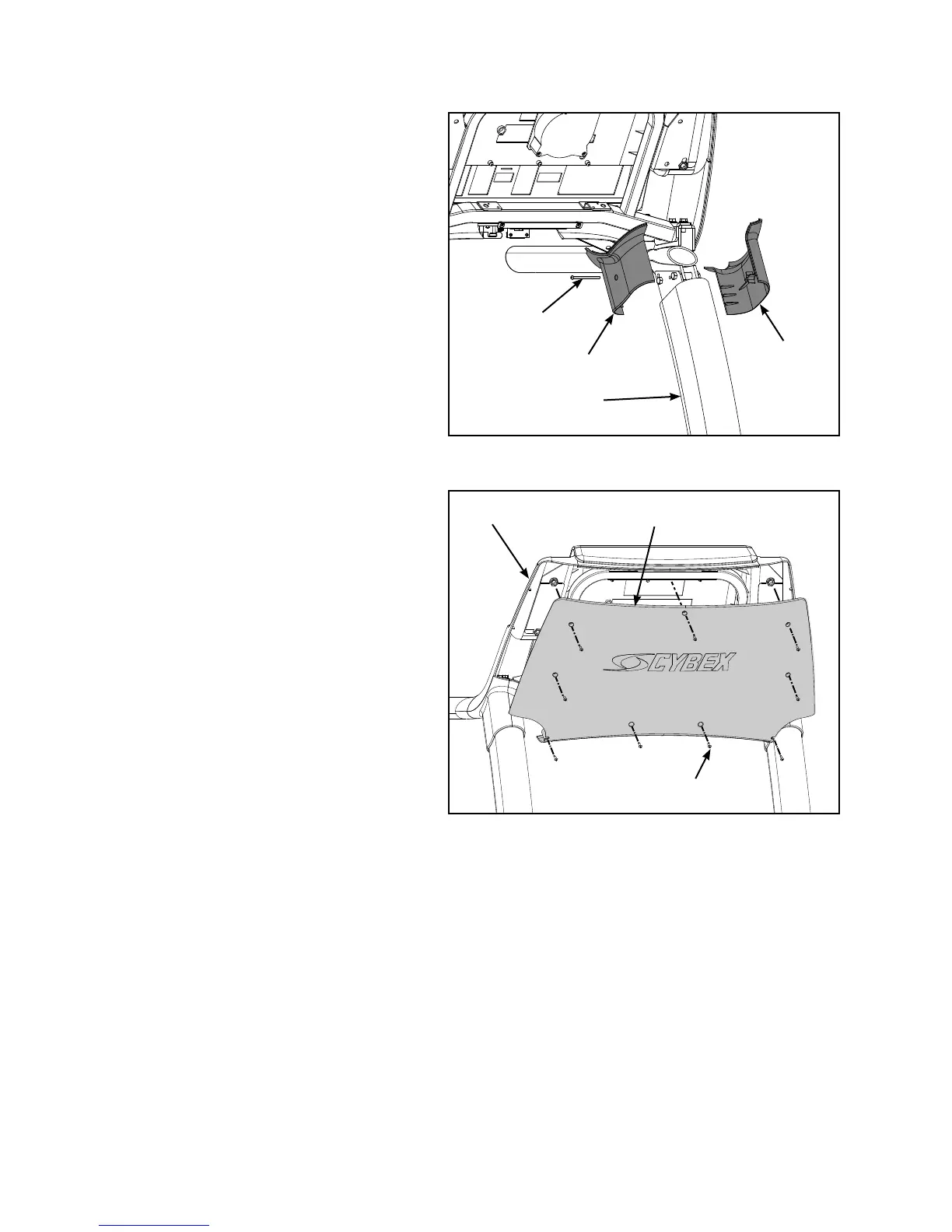
9. Attach the upright covers (four pieces).
Locate the outer left upright cover A.
(#9), inner left upright cover (#10)
and one screw 8/16 x 2.5” (#23).
See Figure 7.
Place the two upright covers in B.
place over the left upright (#3). See
Figure 7.
Insert the screw 8/16 x 2.5” (#23) C.
into the inner left upright cover
(#10) and secure using a Phillips
screwdriver. See Figure 7.
Repeat steps 9A to 9C for the right D.
side.
10. Attach the back console cover.
Locate the back console cover (#13) A.
and nine screws 8/16 x .50” (#21).
See Figure 8.
While being sure not to pinch any B.
cables, use a Philips screwdriver to
secure the nine screws 8/16 x .50”
(#21) that hold the back console cover
(#13) to the console assembly (#2).
See Figure 8.
Figure 8
#13
#21 (9)
Figure 7
#10
#23
#9
#2
#3
 Loading...