Cybex Arc Trainer Owner’s & Service Manual
Page 7-23
Table of Contents . . . . . . . . . iii
7 Service
Warnings/Cautions . . . . . . . 7-1
Test Mode . . . . . . . . . . . . . . 7-2
LED Functions . . . . . . . . . . . 7-3
Key Functions . . . . . . . . . . . 7-3
Error Codes . . . . . . . . . . . . . 7-4
Speed Sensor Adjustment . 7-5
Drive Belts . . . . . . . . . . . . . . 7-7
Eddy Current Brake. . . . . . 7-13
Elevation Motor . . . . . . . . . 7-16
Power Switch . . . . . . . . . . 7-20
Upper Pillow Blocks . . . . . . 7-22
Lower Pillow Blocks . . . . . 7-26
Pedal Arm & Linkage Arm . 7-28
Lower Control Board . . . . . 7-29
Upper Display Board . . . . . 7-31
Contact Heart Rate Board. 7-33
CSAFE Board . . . . . . . . . . 7-35
Upper Display Cable . . . . . 7-36
Lower Display Cable . . . . . 7-38
Display Overlays . . . . . . . . 7-41
Parts List . . . . . . . . . . . . . . 7-43
Exploded Views. . . . . . . . . 7-45
Schematic . . . . . . . . . . . . . 7-51
5. Remove the crank covers.
A. Using a Phillips head screwdriver, remove the three screws securing
each crank cover in place. See Figure 6.
B. Remove both crank covers.
! WARNING: Failure to release the drive belt tension may cause personal
injury and may damage the unit.
6. Release the drive belt tension.
A. Using a 7/16” socket wrench, loosen the two screws on the lower pivot
shaft until the screws are raised 1/2” above the shaft. See Figure 15.
NOTE: The drive belt tension is now released.
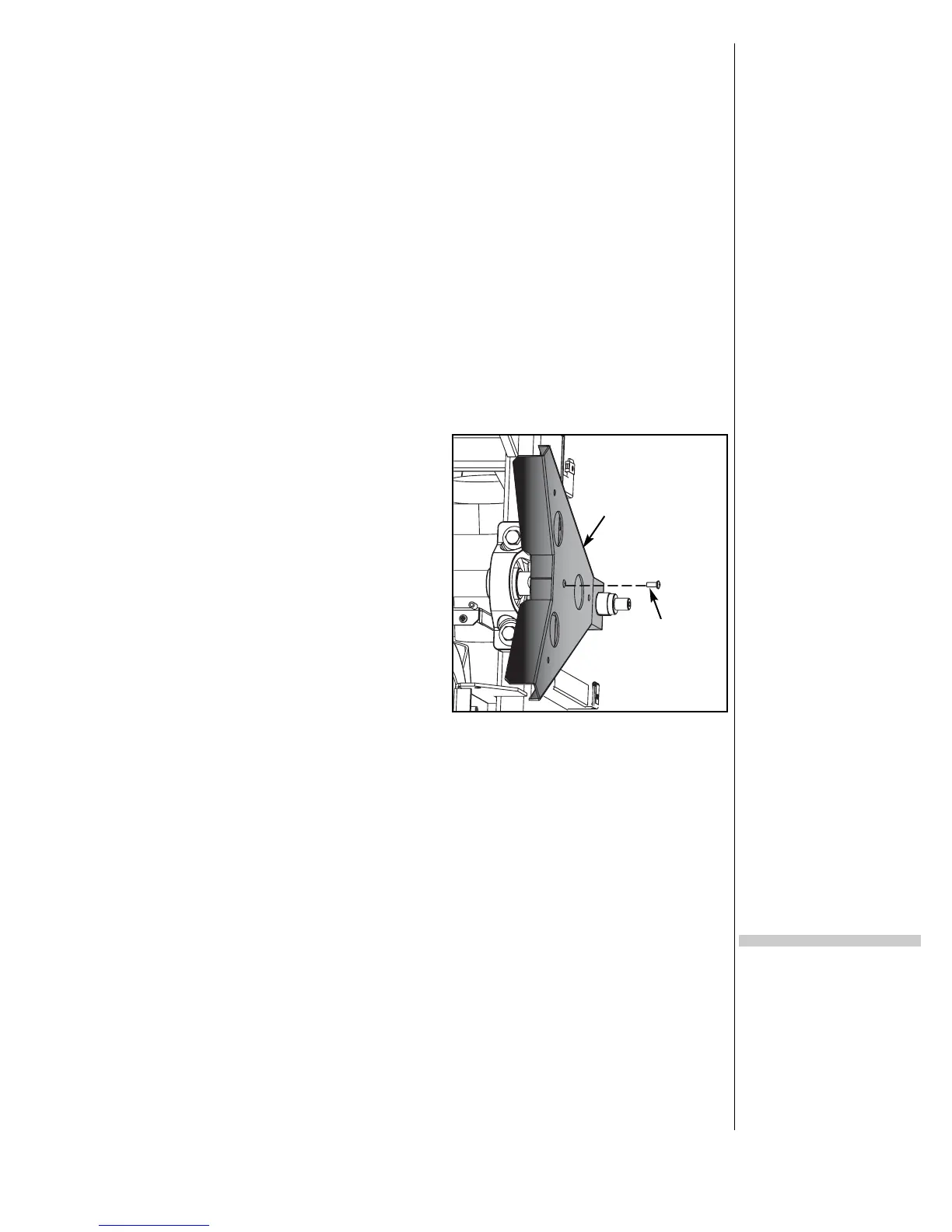
7. Remove the crank arm disk
supports.
A. Using a Phillips head screwdriver,
remove the one screw securing
each crank arm disk support in
place. See Figure 20.
! WARNING: Do not touch components
on the lower board. A
charge can remain after
unplugging the power cord
and turning off the unit.
8. Remove the lower board assembly.
A. Pull out on the lower board shield. NOTE: It will snap out.
B. Disconnect the elevation cable from the lower board.
C. Using a 3/8” nutdriver, remove the nut, washer and ground wire from
the stud above the lower board.
D. Using a Phillips head screwdriver, remove the top two screws from the
lower board assembly and loosen the bottom two screws.
E. Slide the lower board assembly left and off the two bottom screws then
gently suspend it by the cables.
9. Remove the crank arms.
A. Using a 7/16” socket wrench, loosen but do not remove the one screw
on each crank arm. See Figure 21.
B. Remove the crank arms.
Figure 20
Crank Arm Disk
Support (2)
Screw