4. Attach the new display board.
A. Place the display board in position and gently push the display board down into the
CSAFE board connector.
B. Using a Phillips head screwdriver, four screws securing the display board to the
console.
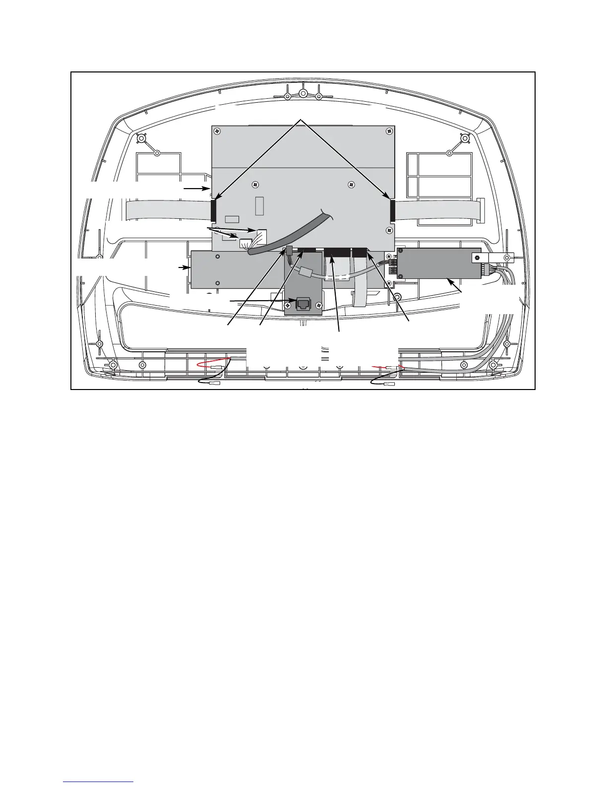
5. Connect the cables.
A. Connect these cables into the display board: the display cable (2 connectors); the two
upper switch membrane connectors; the lower switch membrane connector; the
contact heart rate cable and the upper to lower board jumper. See Figure 25.
6. Check the connections.
A. Check to see that all of the cables are connected firmly in their proper place.
7. Secure the console back.
A. While being sure not to pinch any cables, use a Phillips head screwdriver to tighten
five screws securing the top console back to the console front.
Page 7-32
Cybex Arc Trainer Owner’s & Service Manual
CSAFE Board
Connects to
Display Board
Upper Display Board
Lower Display Board
Contact Heart
Rate Port
Lower Switch
Membrane
Upper to
Lower Board
Jumper
Upper Switch Membrane Ports
Heart Rate
Board
Display Cable Ports
Figure 25 NOTE: This figure does not show handrails or lower console back.
RJ-45 Port