Cypress EZ-USB CX3
EZ-USB® CX3 Technical Reference Manual, Doc. No. 001-91492 Rev. *B 6
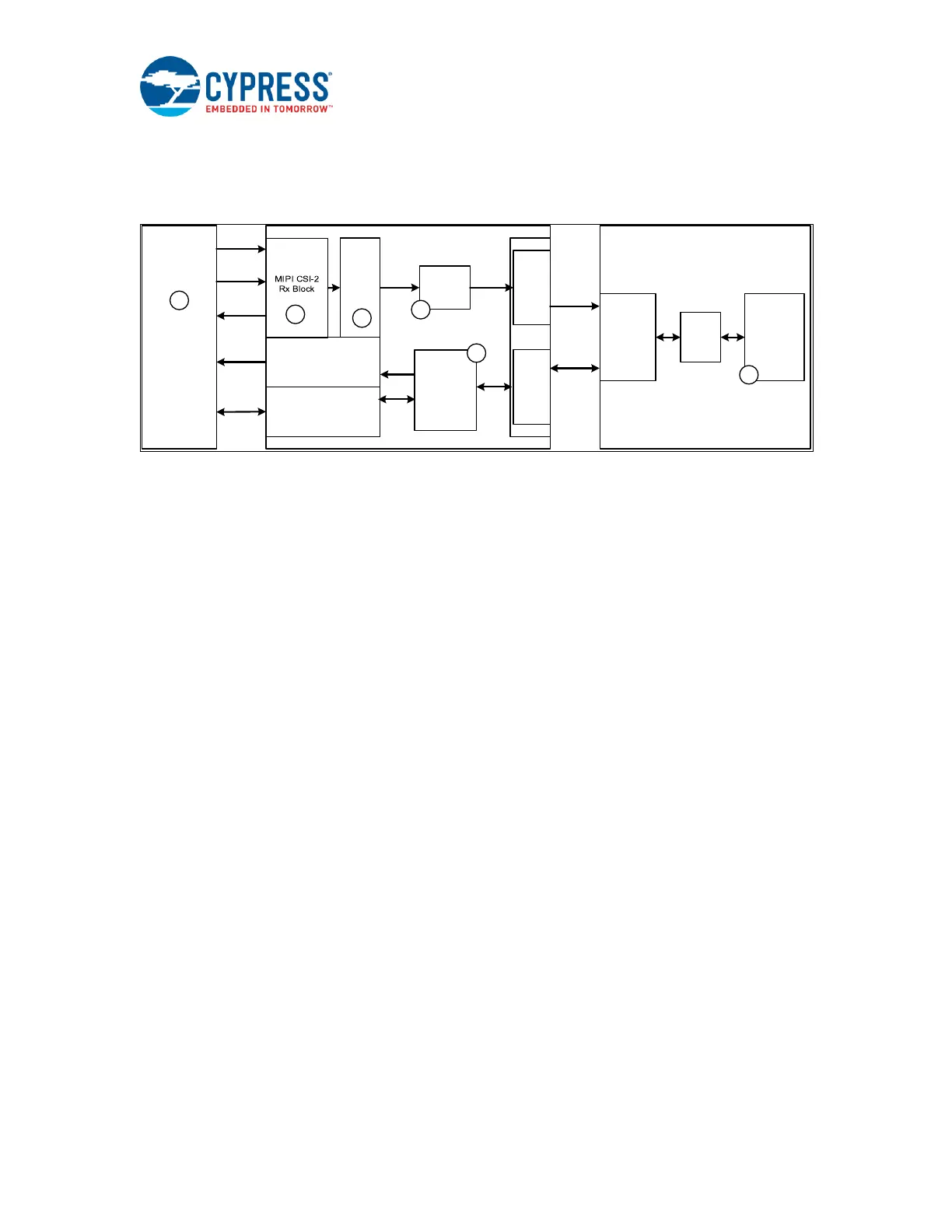
1.3 Block Diagram
Figure 4 is a detailed block diagram of a typical system using CX3 to transfer data from an image
sensor to a USB Host.
Figure 4: System Block Diagram
The main sub-blocks of the block diagram are numbered, and the tasks executed by each sub-block are
described below:
1. The MIPI CSI-2-based image sensor connects to CX3 and is configured using the Camera Control
Interface (I
2
C) bus.
2. The CX3 MIPI CSI-2 receiver block reads the data from the image sensor, de-serializes it, merges lanes,
de-packetizes it, and then sends it as a parallel input to the fixed function GPIF II block.
3. The GPIF II block and its fixed-function state machine make the image sensor data available to the USB
interface using a DMA channel.
4. The DMA channel moves the image data from the GPIF II block to the USB Interface Block (UIB).
5. The CX3 firmware initializes the CX3 hardware blocks, configures the image sensor and MIPI CSI-2
controller, controls the USB interface, and services all USB protocol requests. The CX3 firmware can be
customized to add class-specific headers to the video stream data before it is committed to the USB
interface.
6. A host application such as an image signal processor or a video stream player provides control requests
to configure the video stream and sensor, and processes and renders the video stream on the host PC.

 Loading...


