WEB Client 68
3) Select the period you need to enable and input start time and end time of
corresponding period.
4) If you need to apply this period setting to any other day, select the check box of the
corresponding days.
5) Click OK and make the period of the day valid.
Repeat the steps above and make settings upon any other day.
Make setting upon other parameters. Please refer to Table 5-29 for more details.
Table 5-29 Relay activation parameter description
Input anti-dither time. It ranges from 0s to 100s.
Select relay-in type according to the connected alarm input device.
Optocoupler output, select check box and it will activate corresponding
alarm output device when alarm occurs.
The time that delays alarm when alarm occurs.
Click OK to finish configuration. ,
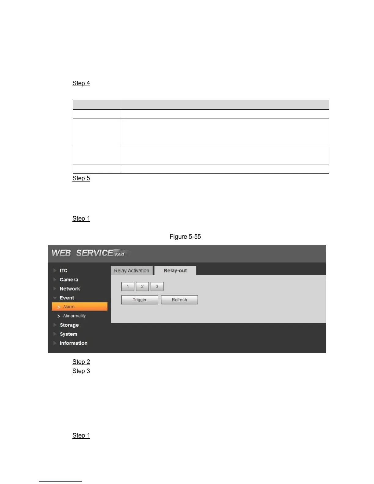
5.4.4.1.2 Relay-out
In this section, it can analog trigger one alarm output signal.
Select Setting > Event > Alarm> Relay-out.
The Relay-out interface is displayed. See Figure 5-55.
Relay-out
Click 1, 2 or 3 and set 1 channel of alarm channel.
Set alarm output
Click Trigger and output relay-out signal
Click Refresh and inquire relay-out status.
5.4.4.2 Abnormality
In this section, you can set relay-out mode of different events.
Select Setting > Event > Abnormality.
 Loading...