5 Technical data
Service manual
101
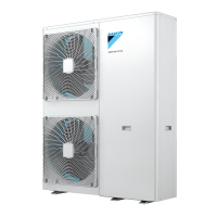
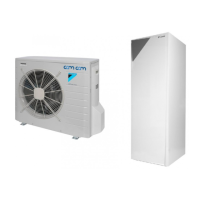
EBLQ+EDLQ011~016CAV3+W1 + EBLQ+EDLQ011~016CA3V3+W1
+ EK(2)CB07CAV3 + EKMBUHCA3V3+9W1
Daikin Altherma – Monobloc
ESIE18-04 – 2019.02
5.2 Wiring diagram
5.2.1 Wiring diagram: Single phase
INFORMATION
The diagrams shown in this manual may be incorrect due
to changes/updates to the unit. Correct diagrams are
supplied with the unit and can also be found in the
technical data book.
See the internal wiring diagram supplied with the unit (on the inside of the front plate). The abbreviations used are listed below.
(1) Connection diagram
English Translation
Connection diagram Connection diagram
Outdoor Outdoor
ON ON
OFF OFF
See note *** See note ***
Upper Fan Upper fan
Lower Fan Lower fan
Injection Injection
Main Main
(2) Layout
English Translation
Front Front
Position of compressor terminal Position of compressor terminal
(3) Notes
English Translation
Notes Notes
Connection
X1M Main terminal
Earth wiring
Field supply
Option
Switch box
PCB
Wiring depending on model
Protective earth
Field wire
NOTES:
1 Refer to the wiring diagram sticker (on the back of the service
cover) for how to use the BS1~BS4 and DS1 switches.
2 When operating, do not short-circuit protective devices S1PH,
S1PL and S1NPH
3 Refer to the combination table and the option manual for how
to connect the wiring to X6A.
4 Colours: BLK: black; RED: red; BLU: blue; WHT: white; GRN:
green; YLW: yellow
5 Confirm the method of setting the selector switches (DS1) by
service manual. Factory setting of all switches: OFF.
(4) Legend
A1P Printed circuit board (main)
A2P (V3 only) Printed circuit board (service)
A2P (W1 only) Printed circuit board (inverter)
A3P Printed circuit board (noise filter)
A4P (V3 only) Printed circuit board (communication)
BS1~BS4 (A2P) Push-button switch
C1~C4 (A1P) (V3
only)
Capacitor
C1~C3 (A2P) (W1
only)
Capacitor
DS1 (A2P) DIP switch
E1H * Bottom plate heater
E1HC Crankcase heater
F1U, F3U, F4U
(A1P~A4P) (V3
only)
Fuse T6.3A 250V
F6U (A1P) (V3
only)
Fuse T5A 250V
F7U, F8U (V3
only)
* Fuse F1A 250V
F1U, F2U (A1P)
(W1 only)
Fuse T31.5A 500V
F3U~F6U (A1P)
(W1 only)
Fuse T6.3A 500V
F7U (A2P) (W1
only)
Fuse T5A 250V
F8U, F9U (W1
only)
* Fuse F1A 250V
H1P~H7P (A2P) LED (service monitor is orange)
HAP (A1P) (V3
only)
LED (service monitor is green)
HAP (A1P~A2P)
(W1 only)
LED (service monitor is green)
K1M~K2M (A2P)
(W1 only)
Magnetic contactor (main-upload)
K1R (A1P) Magnetic relay (Y1S)
K1R (A2P) (W1
only)
Magnetic relay (upload)
K2R (A1P) (V3
only)
Magnetic relay (Y3S)
K3R (A1P) (V3
only)
Magnetic relay (E1H)
K2R (A1P) (W1
only)
Magnetic relay (E1H)
K3R (A1P) (W1
only)
Magnetic relay (Y3S)
K4R (A1P) Magnetic relay (E1HC)
K10R (A1P) (V3
only)
Magnetic relay (upload)
K11R (A1P) (V3
only)
Magnetic relay (main)
L1R (V3 only) Reactor
L1R~L3R (W1
only)
Reactor
 Loading...
