5 Technical data
Service manual
119
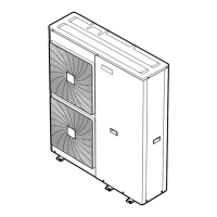
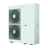
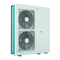
EBLQ+EDLQ011~016CAV3+W1 + EBLQ+EDLQ011~016CA3V3+W1
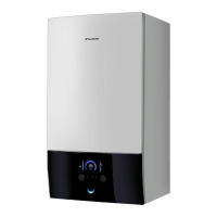
+ EK(2)CB07CAV3 + EKMBUHCA3V3+9W1
Daikin Altherma – Monobloc
ESIE18-04 – 2019.02
INFORMATION
The diagrams shown in this manual may be incorrect due
to changes/updates to the unit. Correct diagrams are
supplied with the unit and can also be found in the
technical data book.
X1M
L1R
U V W
Z8C N=6
RED
WHT
BLK
Z9C
N=1
Z7C N=5
Z3C
N=2
RED
WHT
BLK
BLU
Z4C
N=2
RED
WHT
BLK
Z5C
N=1
Z6C
N=2
RED
WHT
BLK
H1P H2P H3P H4P H5P H6P H7P
HAP
S1NPH
BLK
WHT
RED
GRN
3N~ 50 Hz 400 V AC
Z1C
N=1
Z2C
N=1
GRN
A1P
RED
WHT
BLK
BLU
GRN/YLW
A1P
L2R
L3R
HAP
Y1E
M
M1C
MS
3~
F7U
M1F
MS
3~
1
X106A
2
3 4 5
M2F
MS
3~
1
X107A
2
3 4 5
X517AX516A
X507AX506A
C3
V3R
R2
K1R
X191A
1
2
L4R
2
X109A
1
X108A
1
2
PS
A2P
1
X9A
2 21
X8A
L31AL21AL11A N1A
A3P
L12B L22B L32B
L11B L21B L31B
Z4F
N1B
L3R
L2R
L1R
L12A L22A L32A
K1M
V2R
C2C1
V1R
U V W
R1
K2M
Z2F
Z1F
F1U F2U
L1A L2A L3A NA
F6U
F5U
F4U
F3U
1
X104A
2
3
4
5
1
X105A
2
3
4
5
1
X4A
2
3
4
5
1
X5A
2
3
4
5
DS1
1
OFF
ON
2
BS1 BS2 BS3 BS4
Y3E
M
2
3
4
5
1
X22A
6
1
X21A
2
3
4
5
6
1
X17A
2
3
4
- t°
R6T
1
X13A
2
- t°
R5T
- t°
R4T
- t°
R3T
- t°
R2T
1
X12A
2
3
4
5
6
7
8
1
X11A
2
- t°
R1T
X26A
1
2
1
X32A
2
S1PH
P>
E1H
F9U F8U
X77A
1
2
Y1S Y3S
1
X25A
2 1
X27A
2 1
X28A
2
E1HC
K4RK3RK1R
K2R
1
X1M
2
3
X803A
1
2 3
Z3F
E1
Q1DI
L1 L2 L3 N
X1M
L1 L2
L3
N
E
X6A
1
2 3 4 5 6 7 8 9 10 11 12
X111A
1
2
R7T
- t°
3
A1P/X19A.5
A1P/X19A.3
A1P/X19A.1
(1) Connection diagram
Hydro
SEE NOTE 3
SEE NOTE 3
(2) Layout
Front
Position of compressor terminal
OUTDOOR
OUTDOOR
4D115042
Upper fan Lower fan
Injection
Main
 Loading...
