7 | Unit installation
Installer reference guide
67
ERGA04~08E + EHVH04+08SU18+23E
Daikin Altherma 3 R F
4P629090-1C – 2022.08
PATTERN 1 PATTERN 2 PATTERN 3 PATTERN 4
Restrictions See "PATTERN
1"[467]
See "PATTERN 2 and 3"[467] See "PATTERN
4"[469]
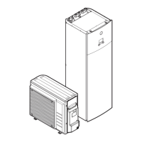
Room A (= room where indoor unit is installed)
Room B (= adjacent room)
a1 Bottom opening for natural ventilation
a2 Top opening for natural ventilation
PATTERN 1
For PATTERN 1 you only need to comply with the spacing guidelines described in "7.1.3 Installation site
requirements of the indoor unit"[464].
PATTERN 2 and 3
For PATTERN 2 and 3, additionally to the spacing guidelines described in "7.1.3Installation site requirements of
the indoor unit"[464], you also need to comply with the minimum floor area requirements as described in the
following flow chart. The flow chart uses the following tables: "16.5Table 1 – Maximum refrigerant charge allowed
in a room: indoor unit" [4 276], "16.6 Table 2 – Minimum floor area: indoor unit" [4 277] and "16.7 Table 3 –
Minimum bottom opening area for natural ventilation: indoor unit"[4277].
INFORMATION
Multiple indoor units. If two or more indoor units are installed in a room, you must
consider the maximum refrigerant charge that can be released in the room when a
SINGLE leak occurs. Example: If two indoor units are installed in the room, each with
its own outdoor unit, then you have to consider the refrigerant charge of the largest
indoor-outdoor combination.
 Loading...