2 Components
Service manual
30
ATXP20~35L2V1B + FTXP20~71L2V1B + ARXP20~35L2V1B +
RXP20~71L2V1B
Split Comfora R32
ESIE18-01 – 2019.02
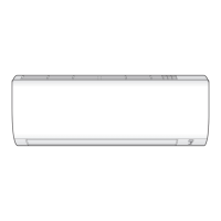
a Fuse
Blown fuse on the indoor unit
PCB?
Action
Yes Replace the blown fuse, see
"2.6.2Repair procedures"on
page30.
No Return to "2.6.1Checking
procedures"on page29 of the
indoor unit PCB and continue
with the next procedure.
Problem solved?
After all checking procedures listed above have been performed:
Is the problem solved? Action
Yes No further actions required.
No Return to the troubleshooting of
the specific error and continue
with the next procedure.
2.6.2 Repair procedures
To adjust the power of the indoor unit PCB
1 Make sure that the power source is in line with the requirements
described in the databook.
Is the problem solved? Action
Yes No further actions required.
No Return to "2.6.1Checking
procedures"on page29 of the
indoor unit PCB and continue
with the next procedure.
To remove the indoor unit PCB
Prerequisite: Turn OFF the unit via the user interface.
Prerequisite: Turn OFF the respective circuit breaker.
Prerequisite: Remove the required plate work, see "2.10 Plate
work"on page35.
1 Disconnect all connectors from the indoor unit PCB.
2 Carefully pull the indoor unit PCB from the PCB supports.
a Indoor unit PCB
b PCB support
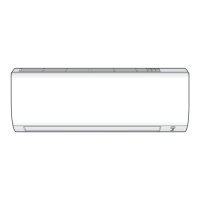
a Indoor unit (power) PCB
b PCB support
c Indoor unit (control) PCB
3 Remove the indoor unit PCB from the indoor unit.
4 To install the indoor unit PCB, see "2.6.2Repair procedures"on
page30.
To install the indoor unit PCB
1 Install the indoor unit PCB in the correct location on the PCB
supports.
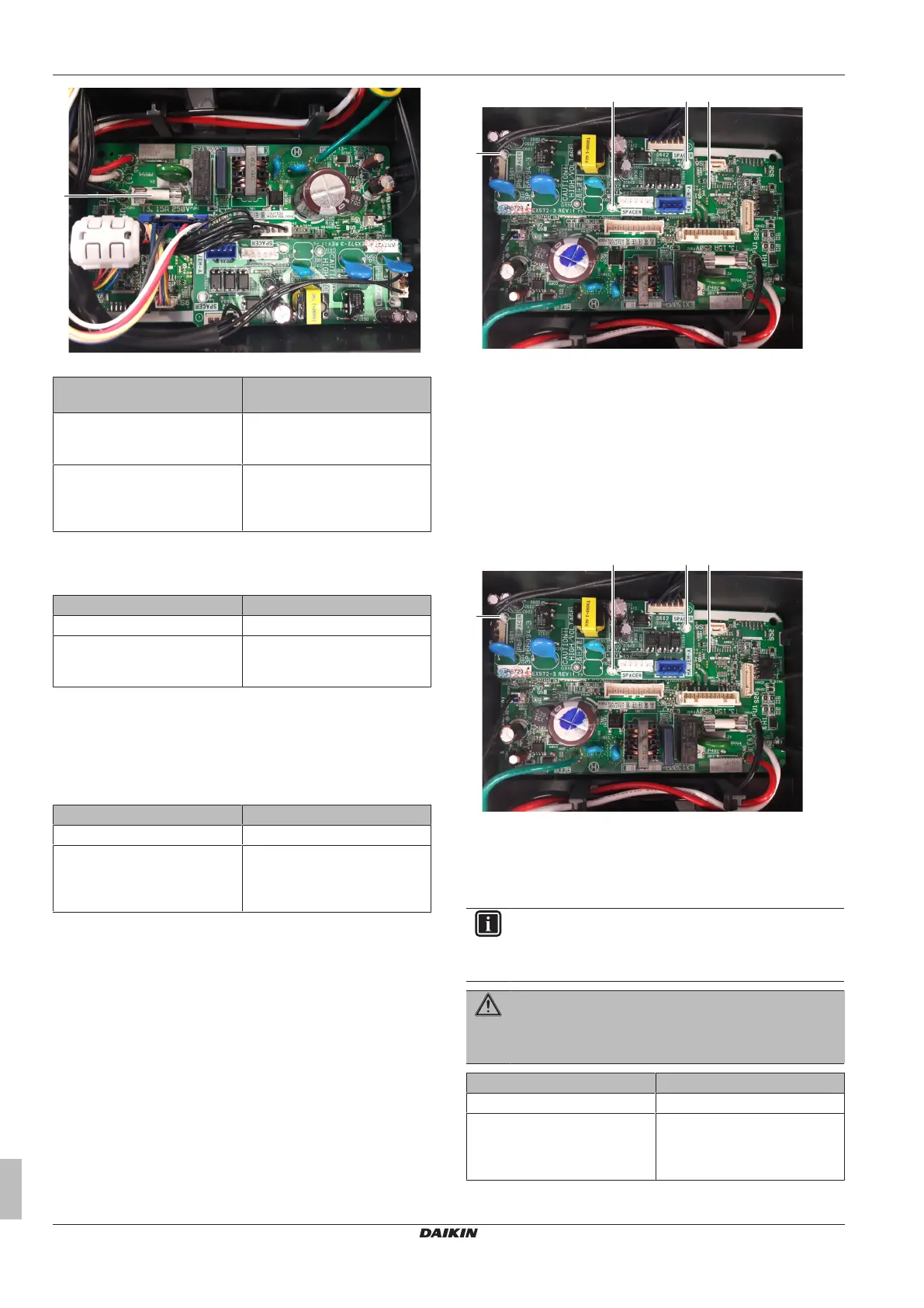
a Indoor unit PCB
b PCB support
a Indoor unit (power) PCB
b PCB support
c Indoor unit (control) PCB
2 Connect all connectors to the indoor unit PCB.
INFORMATION
Use the wiring diagram and connection diagram for correct
installation of the connectors, see "5.2Wiring diagram"on
page50.
WARNING
When reconnecting a connector to the PCB, do NOT apply
force, as this may damage the connector or connector pins
of the PCB.
Is the problem solved? Action
Yes No further actions required.
No Return to "2.6.1Checking
procedures"on page29 of the
indoor unit PCB and continue
with the next procedure.