2 Components
Service manual
42
ATXP20~35L2V1B + FTXP20~71L2V1B + ARXP20~35L2V1B +
RXP20~71L2V1B
Split Comfora R32
ESIE18-01 – 2019.02
2.13.1 Refrigerant thermistors
Checking procedures
INFORMATION
It is recommended to perform the checks in the listed
order.
To perform a mechanical check of the specific thermistor
Prerequisite: Turn OFF the unit via the user interface.
Prerequisite: Turn OFF the respective circuit breaker.
Prerequisite: Remove the required plate work, see "2.10 Plate
work"on page35.
1 Locate the thermistor and remove the insulation if needed.
Check if there is thermal contact between the thermistor and
the piping or ambient.
Is the thermistor correctly
installed (thermal contact
between the thermistor and the
piping)?
Action
Yes Perform an electrical check of the
specific thermistor, see
"Checking procedures"on
page42.
No Correctly install the thermistor,
see "Repair procedures"on
page43.
To perform an electrical check of the specific thermistor
Prerequisite: First perform a mechanical check of the thermistor,
see "Checking procedures"on page42.
1 Locate the thermistor.
2 Measure the temperature using a contact thermometer.
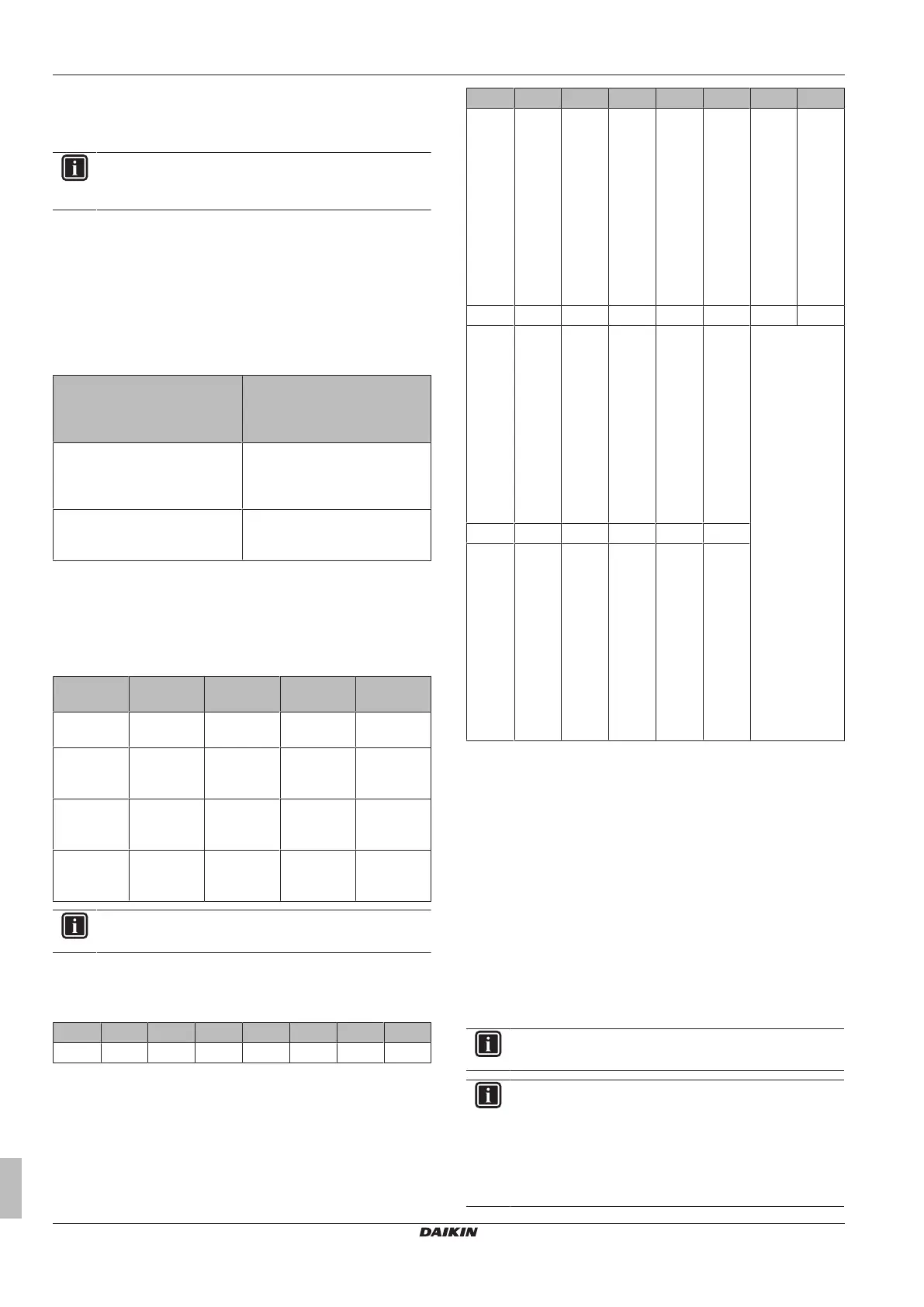
Name Symbol Location
(PCB)
Connector
(pins)
Type
Air
thermistor
R1T Main S90:1‑2 1
Heat
exchanger
thermistor
R2T Main S90:3‑4 1
Discharge
pipe
thermistor
R3T Main S90:5‑6 1
Heat
exchanger
thermistor
R2T Indoor S32:1‑2 1
INFORMATION
The thermistors may vary according to the specific unit.
3 Determine the thermistor resistance that matches the measured
temperature.
Type 1 thermistor
T °C kΩ T °C kΩ T °C kΩ T °C kΩ
–20 197.81 10 39.96 40 10.63 70 3.44
T °C kΩ T °C kΩ T °C kΩ T °C kΩ
–19
–18
–17
–16
–15
–14
–13
–12
–11
186.53
175.97
166.07
156.80
148.10
139.94
132.28
125.09
118.34
11
12
13
14
15
16
17
18
19
38.08
36.30
34.62
33.02
31.50
30.06
28.70
27.41
26.18
41
42
43
44
45
46
47
48
49
10.21
9.81
9.42
9.06
8.71
8.37
8.05
7.75
7.46
71
72
73
74
75
76
77
78
79
3.32
3.21
3.11
3.01
2.91
2.82
2.72
2.64
2.55
–10 111.99 20 25.01 50 7.18 80 2.47
–9
–8
–7
–6
–5
–4
–3
–2
–1
106.03
100.41
95.14
90.17
85.49
81.08
76.93
73.01
69.32
21
22
23
24
25
26
27
28
29
23.91
22.85
21.85
20.90
20.00
19.14
18.32
17.54
16.80
51
52
53
54
55
56
57
58
59
6.91
6.65
6.41
6.65
6.41
6.18
5.95
5.74
5.14
0 65.84 30 16.10 60 4.87
1
2
3
4
5
6
7
8
9
62.54
59.43
56.49
53.71
51.09
48.61
46.26
44.05
41.95
31
32
33
34
35
36
37
38
39
15.43
14.79
14.18
13.59
13.04
12.51
12.01
11.52
11.06
61
62
63
64
65
66
67
68
69
4.70
4.54
4.38
4.23
4.08
3.94
3.81
3.68
3.56
4 Disconnect the thermistor connector from the appropriate PCB.
5 Measure the resistance between the appropriate pins of the
thermistor connector.
6 Check that the measured resistance value matches the
resistance determined through the measured temperature
(earlier step in the procedure). E.g. R1T thermistor:
▪ Measured temperature with contact thermometer: 23.1°C,
▪ Resistance value determined through temperature (using the
table for type 1 thermistors):
Resistance at 23°C: 21.85kΩ,
Resistance at 24°C: 20.90kΩ,
▪ Disconnect connector and measure resistance between S90
pin 1‑2:
Measured resistance: 21.86kΩ,
▪ Measured resistance value is inside the range. R1T
thermistor passes the check.
INFORMATION
All thermistors have a resistance tolerance of 5%.
INFORMATION
The user interface allows to monitor most thermistors.
If the measured resistance value matches the resistance
determined through the measured temperature, but the
temperature for the corresponding thermistor is NOT
correct on the user interface display, replace the applicable
PCB.



 To Next Page