2 Components
Service manual
31
ATXP20~35L2V1B + FTXP20~71L2V1B + ARXP20~35L2V1B +
RXP20~71L2V1B
Split Comfora R32
ESIE18-01 – 2019.02
To adjust the wiring of the indoor unit PCB
1 Adjust the wiring according to the wiring diagram and
connection diagram, see "5.2Wiring diagram"on page50.
2 Check that all connectors are fully plugged‑in. All colour codes
MUST correspond.
3 Check that no connectors are damaged.
Is the problem solved? Action
Yes No further actions required.
No Return to "2.6.1Checking
procedures"on page29 of the
indoor unit PCB and continue
with the next procedure.
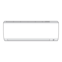
To remove a fuse of the indoor unit PCB
1 Remove the fuse from the PCB.
a Fuse
2 To install a fuse on the indoor unit PCB, see "2.6.2 Repair
procedures"on page30.
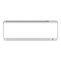
To install a fuse on the indoor unit PCB
1 Install the fuse on the correct location on the PCB.
CAUTION
Make sure the fuse is plugged‑in correctly (contact with the
fuse holder).
a Fuse
Is the problem solved? Action
Yes No further actions required.
Is the problem solved? Action
No Return to "2.6.1Checking
procedures"on page29 of the
indoor unit PCB and continue
with the next procedure.
2.7 Inverter PCB
2.7.1 Checking procedures
As the inverter PCB is integrated in the main PCB of the unit, see
"2.8Main PCB"on page32 for the other check procedures.
To perform an electrical check of the inverter PCB
Prerequisite: Turn OFF the unit via the user interface.
Prerequisite: Turn OFF the respective circuit breaker.
Prerequisite: Remove the required plate work, see "2.10 Plate
work"on page35.
1 Open the compressor insulation.
2 Remove the cover of the compressor wire terminals.
3 Measure the voltage between the pins 7‑4 of the connector
S70. Wait until the voltage drops below 10VDC.
WARNING
The smoothing capacitor MUST discharge below 10VDC
before disconnecting the Faston connectors from the
compressor wiring terminals. Risk of electrocution.
4 Disconnect the Faston connectors from the compressor wire
terminals U, V and W.
INFORMATION
Note the position of the Faston connectors on the
compressor wire terminals to allow correct connection
during installation.
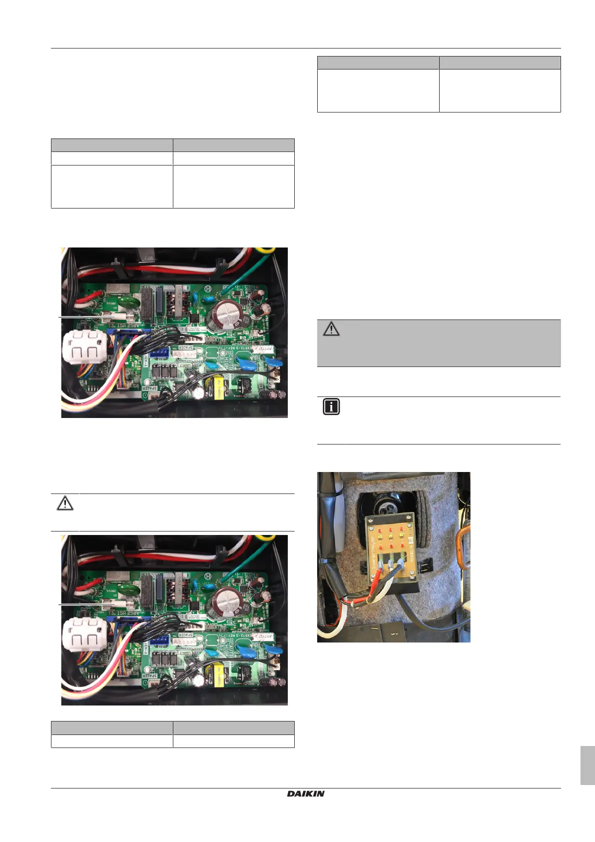
5 Connect the Faston connectors to the Inverter Analyzer (SPP
number 1368521).
6 Turn ON the power of the unit.
7 Locate the switch SW1 on the Inverter Analyzer and press for
5seconds to activate the inverter test.
 Loading...