3 Third party components
Service manual
45
ATXP20~35L2V1B + FTXP20~71L2V1B + ARXP20~35L2V1B +
RXP20~71L2V1B
Split Comfora R32
ESIE18-01 – 2019.02
3.2 Refrigerant circuit
3.2.1 Checking procedures
INFORMATION
It is recommended to perform the checks in the listed
order.
To check if the stop valve is open
Prerequisite: Remove the required plate work, see "2.10 Plate
work"on page35.
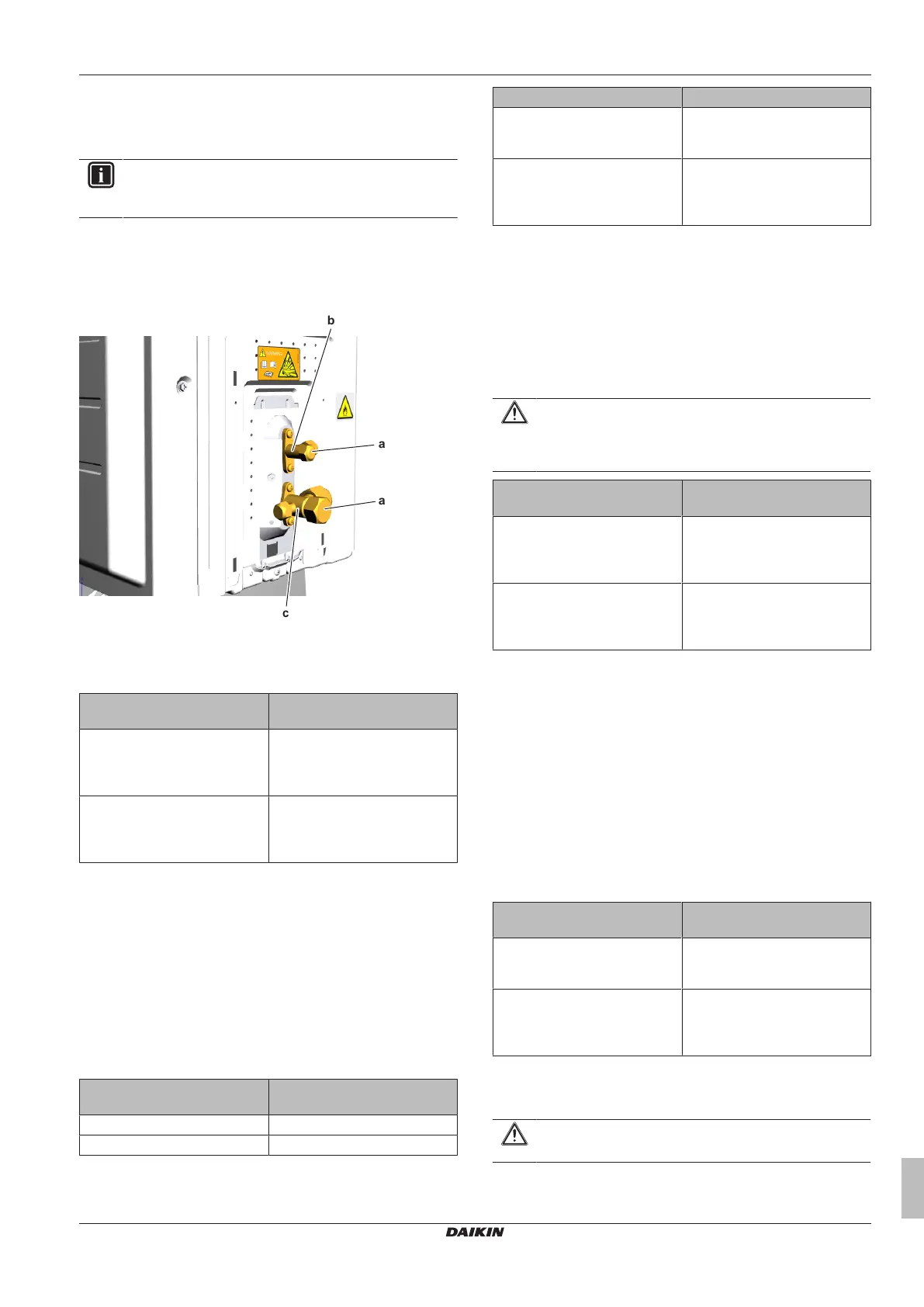
1 Remove the caps.
a Cap
b Liquid stop valve
c Gas stop valve
2 Check if the stop valve is completely open.
The refrigerant circuit stop
valve is open?
Action
Yes Return to "3.2.1Checking
procedures"on page45 of the
refrigerant circuit and continue
with the next procedure.
No Open the stop valve of the
refrigerant circuit, see
"3.2.2Repair procedures"on
page46.
To check if the refrigerant circuit is clogged
Prerequisite: Turn OFF the unit via the user interface.
Prerequisite: Turn OFF the respective circuit breaker.
1 Wait for the refrigerant to reach the outdoor temperature.
2 Connect a manometer to the service port.
3 Measure the low pressure as a reference.
4 Turn ON the power of the unit.
5 Activate Cooling via the user interface.
6 Again measure the low pressure.
Low pressure lower than
expected?
Then
Yes Obstruction is possible.
No Obstruction is less likely.
7 Using a thermometer, check for a temperature drop of minimum
4°C. The obstruction is most likely located where this
temperature drop occurs.
Temperature drop found? Action
Yes Replace the clogged part, see
"3.2.2Repair procedures"on
page46.
No Return to "3.2.1Checking
procedures"on page45 of the
refrigerant circuit and continue
with the next procedure.
To check if the refrigerant circuit is correctly
charged
1 Recuperate all refrigerant from the unit, see "3.2.2 Repair
procedures"on page46.
2 Weigh the recuperated refrigerant.
3 Compare the weight of the recuperated refrigerant with the
logbook of the unit. If the weight does NOT match the logbook,
the refrigerant circuit is charged incorrectly.
CAUTION
Make sure that the original calculation of refrigerant is
correct. (e.g. take into account that due to additional
piping, additional refrigerant could be required).
Is the refrigerant circuit
charged correctly?
Action
Yes Return to "3.2.1Checking
procedures"on page45 of the
refrigerant circuit and continue
with the next procedure.
No Add or recuperate refrigerant
until correctly charged, see
"3.2.2Repair procedures"on
page46.
To check for non-condensables in the refrigerant
circuit
Prerequisite: Turn OFF the unit via the user interface.
Prerequisite: Turn OFF the respective circuit breaker.
1 Wait for the refrigerant to reach the outdoor temperature.
2 Connect a manometer to the service port.
3 Measure the pressure of the refrigerant. The measured
pressure MUST be in line with the expected pressure at outdoor
temperature.
4 If the measured pressure is higher than the expected pressure
(at outdoor temperature), other non‑condensables are mixed in
the refrigerant.
Any non‑condensables found
in the refrigerant circuit?
Action
Yes To replace the refrigerant, see
"3.2.2Repair procedures"on
page46.
No Return to "3.2.1Checking
procedures"on page45 of the
refrigerant circuit and continue
with the next procedure.
To perform a pressure test of the refrigerant circuit
1 Perform a pressure test in line with local legislation.
CAUTION
Perform a pressure test only when leaks are expected.