5 Technical data
Service manual
54
ATXP20~35L2V1B + FTXP20~71L2V1B + ARXP20~35L2V1B +
RXP20~71L2V1B
Split Comfora R32
ESIE18-01 – 2019.02
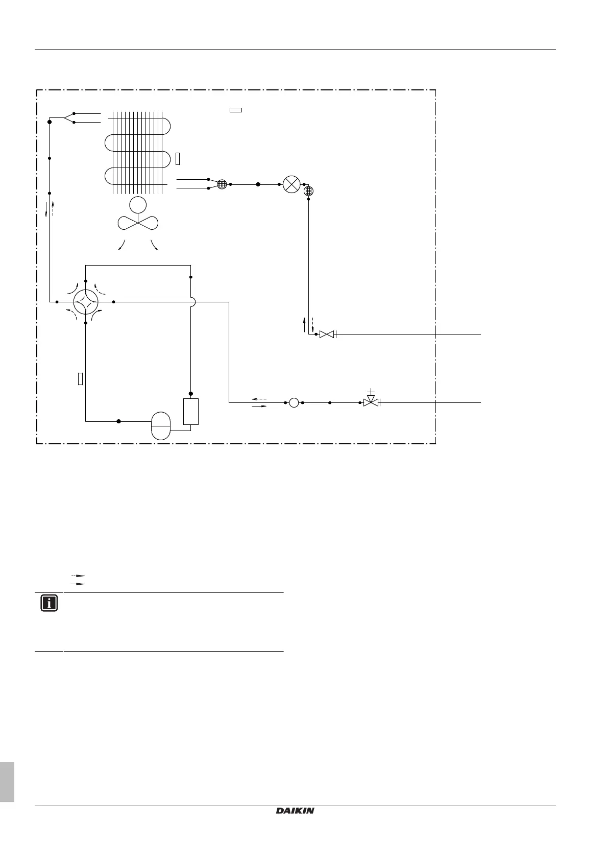
5.3.2 Piping diagram: Outdoor unit
Class 20~35
7.0CuT
7.0CuT
9.5CuT
9.5CuT
4.8CuT
4.8CuT
6.4CuT
6.4CuT
4.8CuT
(6.4CuT)
(9.5CuT)
9.5CuT
9.5CuT
9.5CuT
9.5CuT
7.9CuT
9.5CuT
9.5CuT
9.5CuT
a
b
c
d
e
e
f
g
h
M1C
M1F
R1T
R2T
R3T
Y1E
Y1S
a Field piping (liquid: Ø6.4mm flare connection)
b Field piping (gas: Ø9.5mm flare connection)
c Stop valve (liquid)
d Stop valve with service port (gas)
e Muffler with filter
f Heat exchanger
g Accumulator
h Muffler
M1C Compressor
M1F Fan
R1T Thermistor (outdoor air)
R2T Thermistor (heat exchanger)
R3T Thermistor (compressor discharge)
Y1E Electronic expansion valve
Y1S Solenoid valve (4‑way valve)(ON: cooling)
Heating
Cooling
INFORMATION
The diagrams shown in this manual may be incorrect due
to changes/updates to the unit. Correct diagrams are
supplied with the unit and can also be found in the
technical data book.
 Loading...