2 Components
Service manual
38
ATXP20~35L2V1B + FTXP20~71L2V1B + ARXP20~35L2V1B +
RXP20~71L2V1B
Split Comfora R32
ESIE18-01 – 2019.02
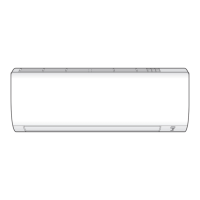
a Electrical power supply wiring
b Wire terminals
c Screws
d Wire clamp
e Screws
f Right side plate assembly
3 Connect the electrical power supply wiring to the wire terminals.
4 Install the wire clamp and fix it using the screws.
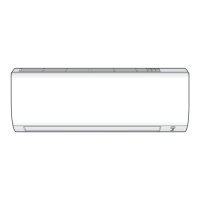
5 Connect all connectors to the main PCB.
INFORMATION
Use the wiring diagram and connection diagram for correct
installation of the connectors, see "5.2Wiring diagram"on
page50.
WARNING
When reconnecting a connector to the PCB, do NOT apply
force, as this may damage the connector or connector pins
of the PCB.
6 Fix the wiring to the switch box using a new cable tie.
a Cable tie
b Switch box
7 Install the insulation on the upper side of the switch box.
a Insulation
b Main PCB
2.10.2 Indoor unit
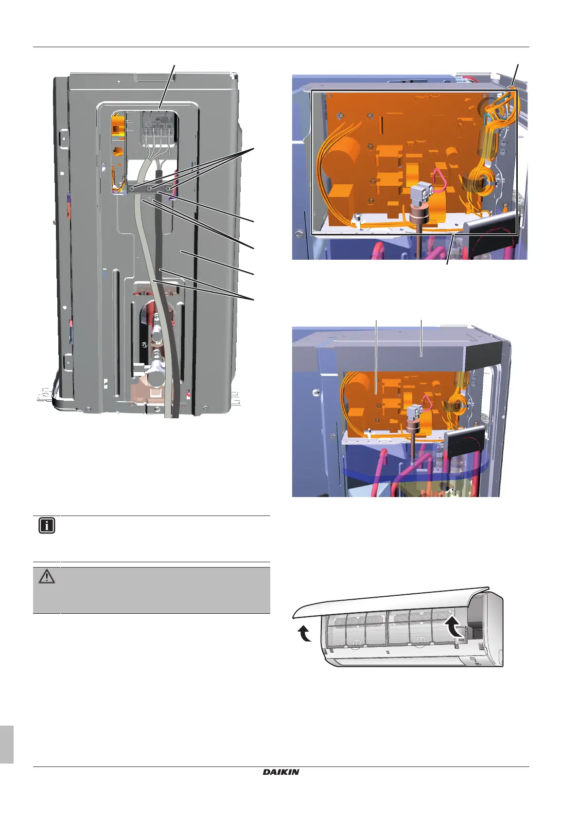
To open the front panel
1 Hold the front panel by the panel tabs on both sides and open
it.
To close the front panel
1 Install the air filters and the titanium apatite deodorizing filters
back in their original positions.
2 Gently press the front panel at both sides and at the center until
it clicks.
 Loading...