1 Troubleshooting
Service manual
6
ATXP20~35L2V1B + FTXP20~71L2V1B + ARXP20~35L2V1B +
RXP20~71L2V1B
Split Comfora R32
ESIE18-01 – 2019.02
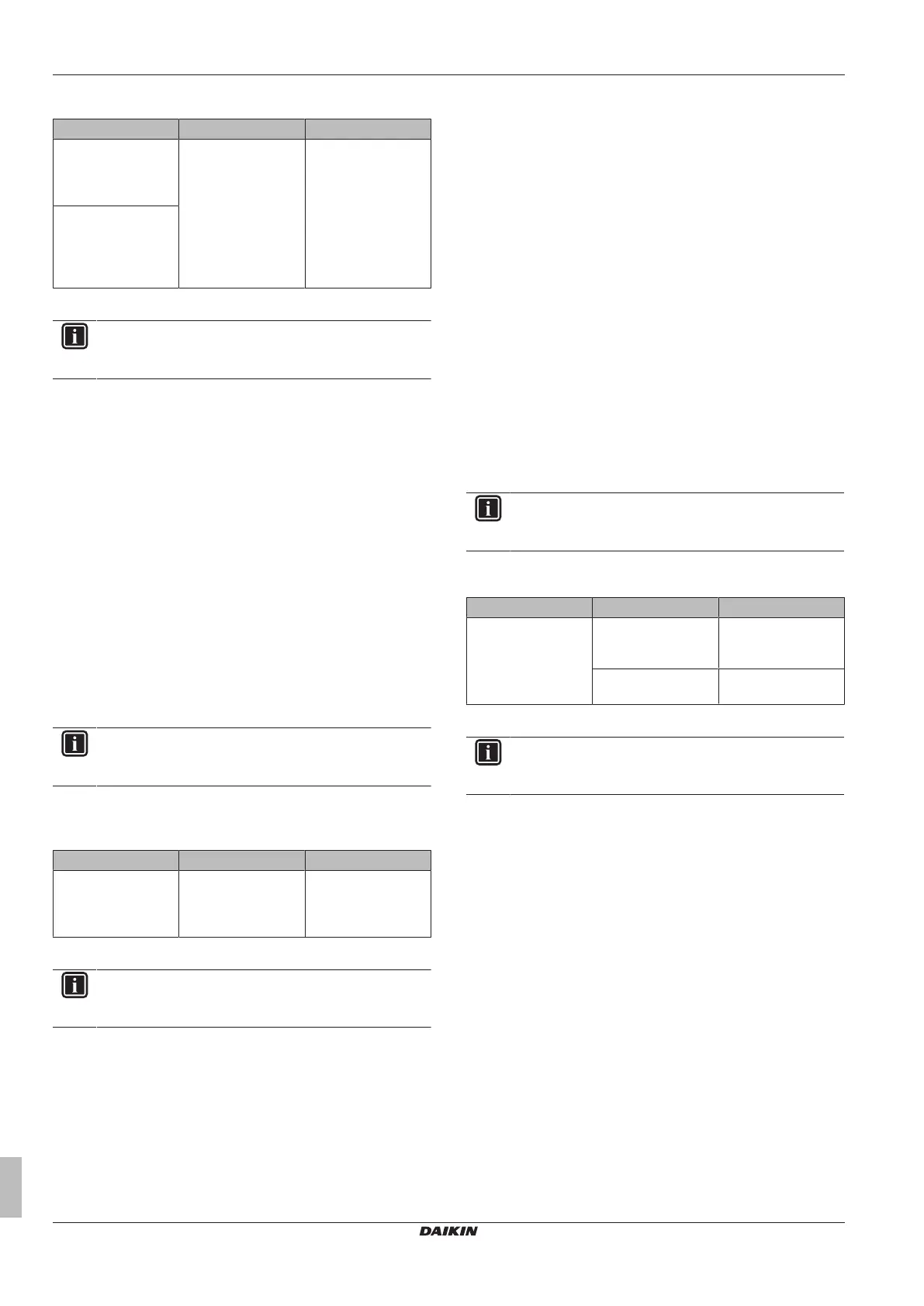
1.5.7 E3-00 – High pressure switch abnormality
Trigger Effect Reset
High pressure switch
opens due to
measured pressure
>41.7bar.
Unit will stop
operating.
Manual reset via user
interface.
High pressure control
(measured pressure
>38bar) occurs 16
times within
300minutes.
To solve the error code
INFORMATION
It is recommended to perform the checks in the listed
order.
1 Perform a check of the high pressure switch. See "2.4 High
pressure switch"on page26.
Possible cause: Faulty high pressure switch.
2 Perform a check of the main PCB. See "2.8 Main PCB" on
page32.
Possible cause: Faulty main PCB.
3 Perform a check of the refrigerant circuit. See "3.2 Refrigerant
circuit"on page45.
Possible cause:
▪ Stop valve is closed,
▪ Clogged refrigerant circuit,
▪ Refrigerant circuit NOT charged correctly,
▪ Humidity in the refrigerant circuit,
▪ Non-condensables in the refrigerant circuit,
▪ Leaking refrigerant circuit.
4 Perform a check of the outdoor unit fan motor. See
"2.9Outdoor unit fan motor"on page34.
Possible cause: Faulty outdoor unit fan motor.
INFORMATION
If all procedures listed above have been performed and the
problem is still present, contact the helpdesk.
1.5.8 E5-00 – Overheat of inverter compressor
motor
Trigger Effect Reset
Compressor overload
is detected.
Unit will NOT stop
operating.
Automatic reset if the
unit runs without
warning for
60seconds.
To solve the error code
INFORMATION
It is recommended to perform the checks in the listed
order.
1 Perform a check of the discharge pipe thermistor. See
"2.13Thermistors"on page41.
Possible cause: Faulty discharge pipe thermistor.
2 Perform a check of the outdoor unit fan motor. See
"2.9Outdoor unit fan motor"on page34.
Possible cause: Faulty outdoor unit fan motor.
3 Perform a check of the compressor. See "2.2Compressor"on
page20.
Possible cause: Faulty compressor.
4 Perform a check of the expansion valve. See "2.3 Expansion
valve"on page23.
Possible cause: Faulty expansion valve.
5 Perform a check of the 4‑way valve. See "2.1 4-way valve"on
page18.
Possible cause: Faulty 4‑way valve.
6 Perform a check of the main PCB. See "2.8 Main PCB" on
page32.
Possible cause: Faulty main PCB.
7 Perform a check of the inverter PCB. See "2.7Inverter PCB"on
page31.
Possible cause: Faulty power module = inverter PCB.
8 Perform a check of the refrigerant circuit. See "3.2 Refrigerant
circuit"on page45.
Possible cause:
▪ Stop valve is closed,
▪ Clogged refrigerant circuit,
▪ Refrigerant circuit NOT charged correctly,
▪ Humidity in the refrigerant circuit,
▪ Non-condensables in the refrigerant circuit,
▪ Leaking refrigerant circuit.
INFORMATION
If all procedures listed above have been performed and the
problem is still present, contact the helpdesk.
1.5.9 E6-00 – Compressor startup defect
Trigger Effect Reset
The motor rotor does
NOT rotate when the
compressor is
energized.
Unit will NOT stop
operating.
Automatic reset after
a continuous run for
10minutes.
Unit will stop
operating
Manual reset via user
interface.
To solve the error code
INFORMATION
It is recommended to perform the checks in the listed
order.
1 Perform a check of the discharge pipe thermistor. See
"2.13Thermistors"on page41.
Possible cause: Faulty discharge pipe thermistor.
2 Perform a check of the refrigerant circuit. See "3.2 Refrigerant
circuit"on page45.
Possible cause:
▪ Stop valve is closed,
▪ Clogged refrigerant circuit,
▪ Refrigerant circuit NOT charged correctly,
▪ Humidity in the refrigerant circuit,
▪ Non-condensables in the refrigerant circuit,
▪ Leaking refrigerant circuit.
3 Perform a check of the compressor. See "2.2Compressor"on
page20.
Possible cause: Faulty compressor.
4 Perform a check of the main PCB. See "2.8 Main PCB" on
page32.
Possible cause: Faulty main PCB.
5 Perform a check of the inverter PCB. See "2.7Inverter PCB"on
page31.
Possible cause: Faulty power module = inverter PCB.