5 Technical data
Service manual
50
ATXP20~35L2V1B + FTXP20~71L2V1B + ARXP20~35L2V1B +
RXP20~71L2V1B
Split Comfora R32
ESIE18-01 – 2019.02
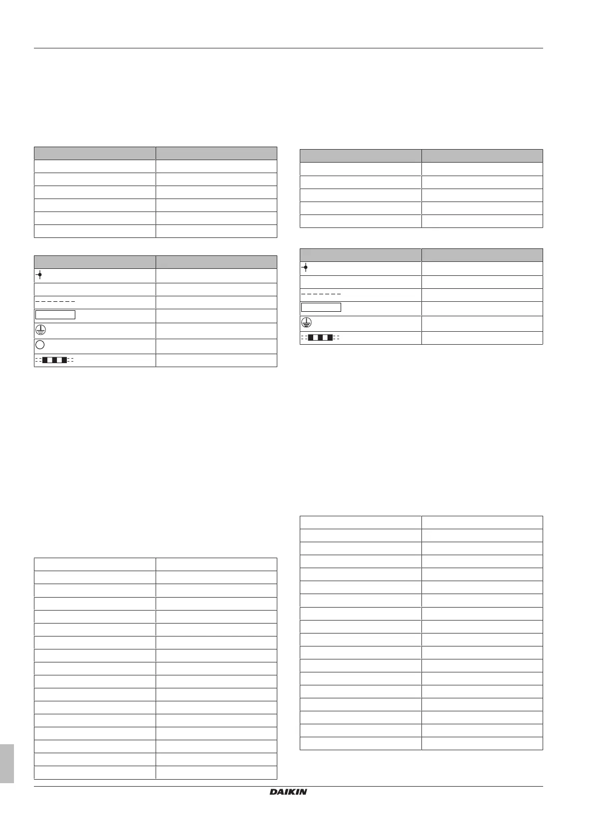
5.2 Wiring diagram
5.2.1 Wiring diagram: Indoor unit
The wiring diagram is delivered with the unit, located inside of the outdoor unit (bottom side of the top plate).
Class 20~35
(1) Wiring diagram
English Translation
Wiring diagram Wiring diagram
Indoor Indoor
Outdoor Outdoor
Transmission circuit Transmission circuit
Signal receiver Signal receiver
Wireless remote control Wireless remote control
(2) Notes
English Translation
Connection
X1M Main terminal
Field supply
PCB
Protective earth
Rectifier
Field wire
NOTES:
BLK : Black
BLU : Blue
BRN : Brown
GRN : Green
ORG : Orange
PNK : Pink
RED : Red
WHT : White
YLW : Yellow
Caution
When the main power is turned off and then back on again,
operation will resume automatically.
(3) Legend
BZ Buzzer
FG Frame ground
FU1 Fuse
H* Harness
IPM* Intelligent power module
LED 1, LED 2 Light‑emitting diode
M1F Fan motor
M1S Swing flap motor
MR* Magnetic relay
PCB1, PCB2, PCB3 Printed circuit board
R1T Room thermistor
R2T Suction pipe thermistor
S6-S602 Connector
S1W Operation switch
V2 Varistor
X1M Terminal strip
Z*C Ferrite core
Class 50~71
(1) Wiring diagram
English Translation
Wiring diagram Wiring diagram
Indoor Indoor
Outdoor Outdoor
Transmission circuit Transmission circuit
Wireless remote control Wireless remote control
(2) Notes
English Translation
Connection
X1M Main terminal
Field supply
PCB
Protective earth
Field wire
NOTES:
BLK : Black
RED : Red
BLU : Blue
WHT : White
GRN : Green
YLW : Yellow
ORG : Orange
Caution
When the main power is turned off and then back on again,
operation will resume automatically.
(3) Legend
FG, HE, S6~S900 Connector
F1U (FU1) Fuse
T1R (L301) Transformer
M1F Fan motor
M1S Swing flap motor
K1R (MR10) Magnetic relay
A*P Printed circuit board
R1T, R2T Thermistor
BS1 (S1W ) Operation switch
R2V (V2) Varistor
X1M Terminal strip
Z*C Ferrite core
IPM* Intelligent power module
H*P (LED*) Pilot lamp
V1R (DB301) Diode bridge
H1O (BZ) Buzzer
C* Capacitor
SR (WLU) Signal receiver