3 Third party components
Service manual
46
ATXP20~35L2V1B + FTXP20~71L2V1B + ARXP20~35L2V1B +
RXP20~71L2V1B
Split Comfora R32
ESIE18-01 – 2019.02
Is the pressure in the
refrigerant circuit correct?
Action
Yes Return to "3.2.1Checking
procedures"on page45 of the
refrigerant circuit and continue
with the next procedure.
No Replace the leaking part of the
refrigerant circuit, see
"3.2.2Repair procedures"on
page46.
Problem solved?
After all checking procedures listed above have been performed:
Is the problem solved? Action
Yes No further actions required.
No Return to the troubleshooting of
the specific error and continue
with the next procedure.
3.2.2 Repair procedures
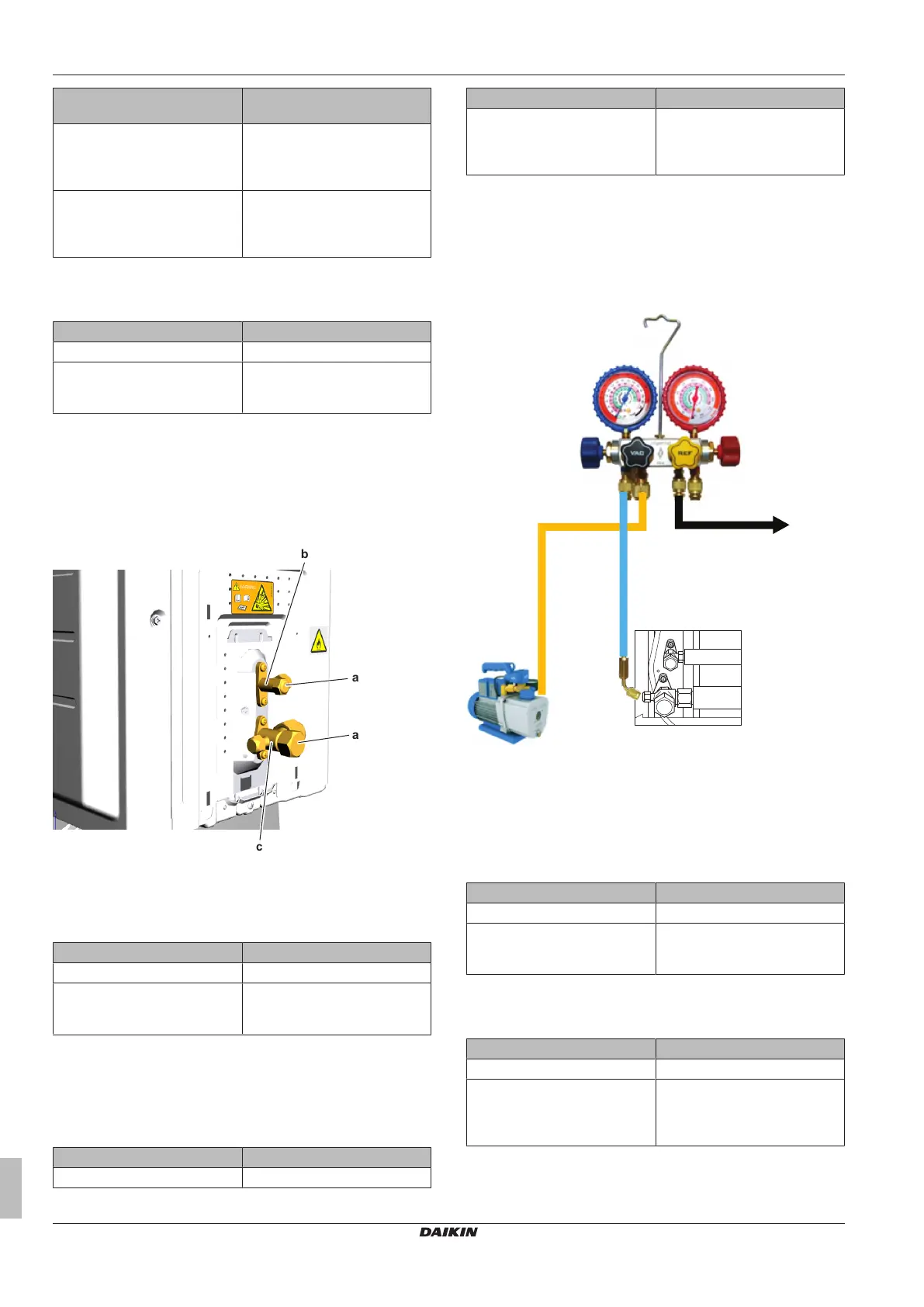
To open the stop valve of the refrigerant circuit
Prerequisite: Remove the required plate work, see "2.10 Plate
work"on page35.
1 Remove the caps.
a Cap
b Liquid stop valve
c Gas stop valve
2 Completely open the stop valve by screwing the stop valve
screw counterclockwise.
Is the problem solved? Action
Yes No further actions required.
No Return to the troubleshooting of
the specific error and continue
with the next procedure.
To replace the clogged/leaking part of the
refrigerant circuit
1 See the correct procedure for the component that needs to be
repaired. See also "Repair information" on page 47 for more
details.
Is the problem solved? Action
Yes No further actions required.
Is the problem solved? Action
No Return to "3.2.1Checking
procedures"on page45 of the
refrigerant circuit and continue
with the next procedure.
To recuperate the refrigerant
Prerequisite: Turn OFF the unit via the user interface.
1 Manually open the expansion valve.
2 Connect the vacuum pump, manifold, recovery unit, and
refrigerant bottle to the service port of the refrigerant circuit as
shown below.
a Vacuum pump
b Connect flexible hose to service port 3 stop valve
c To recovery pump
L Low pressure
H High pressure
V Vacuum
R Refrigerant
3 To add refrigerant, see "3.2.2Repair procedures"on page46.
Is the problem solved? Action
Yes No further actions required.
No Return to the troubleshooting of
the specific error and continue
with the next procedure.
To add refrigerant
1 See the installer reference guide for the correct procedure.
Is the problem solved? Action
Yes No further actions required.
No Perform a pressure test of the
refrigerant circuit, see
"3.2.1Checking procedures"on
page45.