11
Application Information
Installation Guideline
Sharp edges and coil surfaces are potential injury hazard. Avoid from contact with them.
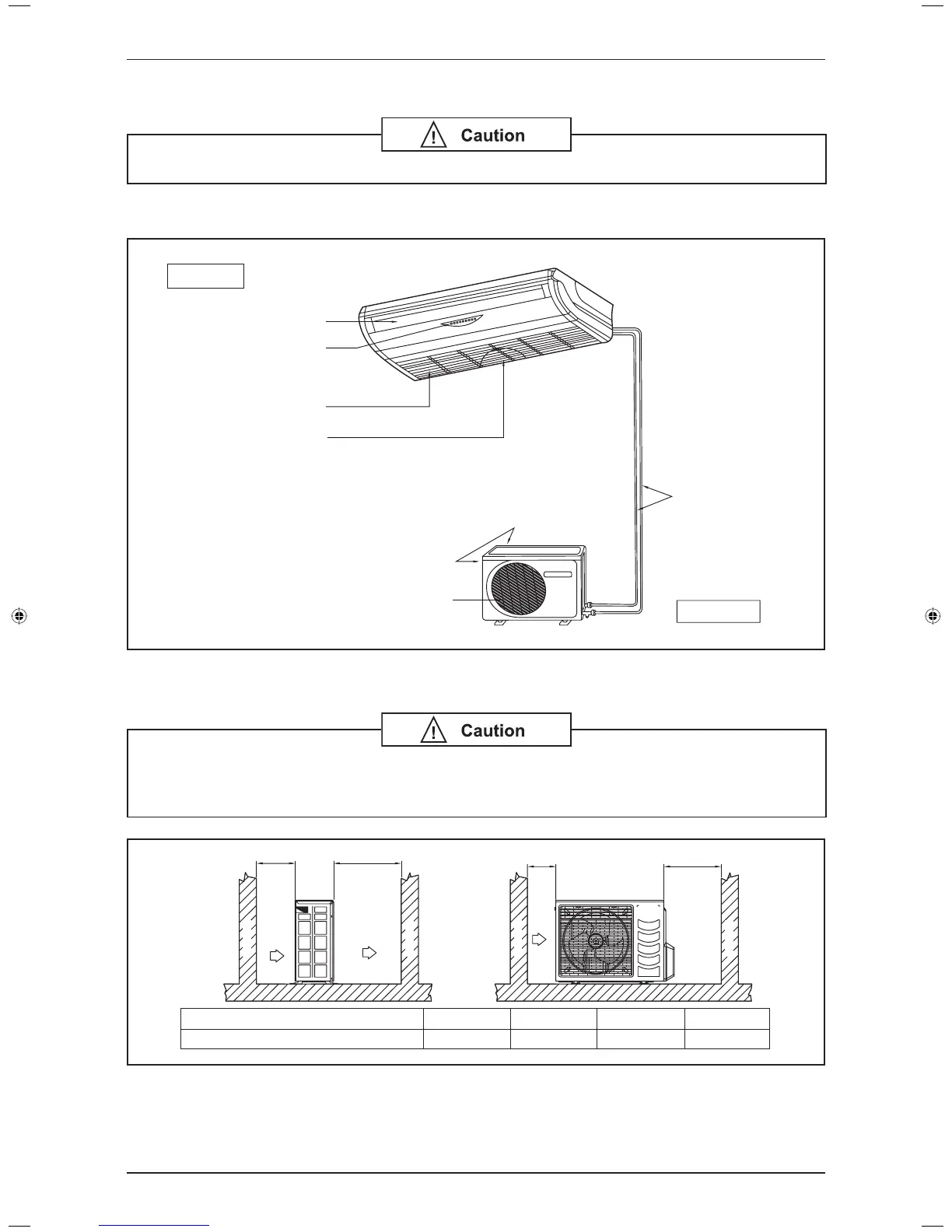
Installation Diagram
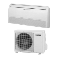
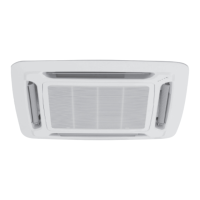
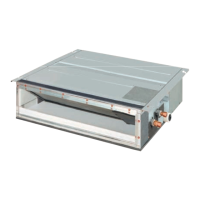
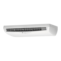
Indoor Unit
Outdoor Unit
Air Discharge Louver
Signal Receiver
Indicator Lights
Air Intake Grille
Air Intake
Refrigerant piping
Air Intake
Air Intake Nozzle
Air Filters
(Inside Air Intake Grille)
Outdoor Clearance
If the condensing unit is operated in an atmosphere containing oils (including machine
oils), salt (coastal area), sulphide gas (near hot spring, oil refi nery plant), such as
substances may lead to failure of the unit.
A
AIR INLET
AIR DISCHARGE
B
OBSTACLE
OBSTACLE
C
AIR INLET
SERVICE SPACE
D
OBSTACLE
OBSTACLE
ALL MODELS
Minimum Distance
A
300 mm
B
1000 mm
C
300 mm
D
500 mm
DAIKIN_FL(Y).indb 11DAIKIN_FL(Y).indb 11 9/27/2012 12:13:19 PM9/27/2012 12:13:19 PM