SiUS281811EA Refrigerant Circuit (Piping Diagrams)
Part 2 Refrigerant Circuit 73
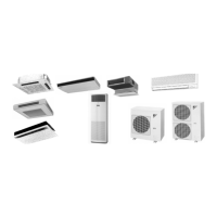
1.3 Indoor Unit
∗1. R1T is for remote controller thermistor or optional remote sensor.
No. in piping
diagram
Name
Symbol
Function
FCQ-TA
FHQ-P
FHQ-M
FAQ-TA
FBQ-P FTQ-TA
(1)
Electronic expansion valve
Y1E Y1E Y1E
Used for gas superheated degree
control while in cooling or subcooled
degree control while in heating.
(2) Suction air thermistor R1T R1T R1T(∗1) Used for thermostat control.
(3)
Liquid pipe thermistor
R2T R2T R2T
Used for gas superheated degree
control while in cooling or subcooled
degree control while in heating.
(4)
Gas pipe thermistor
R3T R3T R3T
Used for gas superheated degree
control while in cooling.
(5)
Discharge air thermistor
—R4T—
Used for discharge air temperature
control.
FCQ-TA, FAQ-TA FHQ-P, FHQ-M
FBQ-P FTQ-TA
Indoor heat exchanger
Fan
Filter Filter
(4)
(2)
(1)
(3)
Gas piping
connection port
Liquid piping
connection port
C: 4D034245R
C: 4D024460P
(4)
(3)
Indoor heat exchanger
Fan
Filter Filter(1)
Gas piping
connection port
Liquid piping
connection port
(2)
Indoor heat exchanger
Fan
Filter Filter
(4)
(2)
(1)
(3)
Gas piping
connection port
Liquid piping
connection port
C: 4D034245R
(5)
C: 4D068194
(4)
(1)
(3)

 Loading...


