2 | Components
Service manual
65
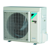
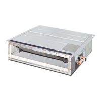
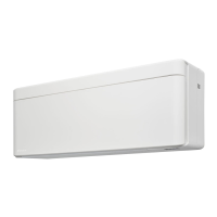
(C)(F)TXA15~50A(W)(S)(T) + (C)(F)TXA15~50B(B)(S)(T) + RXA42+50A +
RXA20~35A + RXA42+50B
Split Stylish R32
ESIE18-03C – 2020.02
a High pressure switch
b Faston connector
c High pressure switch pipe
3 Cut the high pressure switch pipe using a pipe cutter.
4 Remove the high pressure switch from the unit.
5 Supply nitrogen to the refrigerant circuit. The nitrogen pressure MUST NOT
exceed 0.02MPa.
6 Heat the end of the high pressure switch pipe using an oxygen acetylene torch
and remove the high pressure switch pipe end.
7 Stop the nitrogen supply when the piping has cooled down.
8 To install the high pressure switch, see "2.5.2Repair procedures"[464].
To install the high pressure switch
1 Install the high pressure switch in the correct location.
2 Supply nitrogen to the refrigerant circuit. The nitrogen pressure MUST NOT
exceed 0.02MPa.
3 Wrap a wet rag around the high pressure switch and solder the high pressure
switch pipe to the high pressure switch.
a High pressure switch
b Faston connector
c High pressure switch pipe
 Loading...
