2 | Components
Service manual
71
(C)(F)TXA15~50A(W)(S)(T) + (C)(F)TXA15~50B(B)(S)(T) + RXA42+50A +
RXA20~35A + RXA42+50B
Split Stylish R32
ESIE18-03C – 2020.02
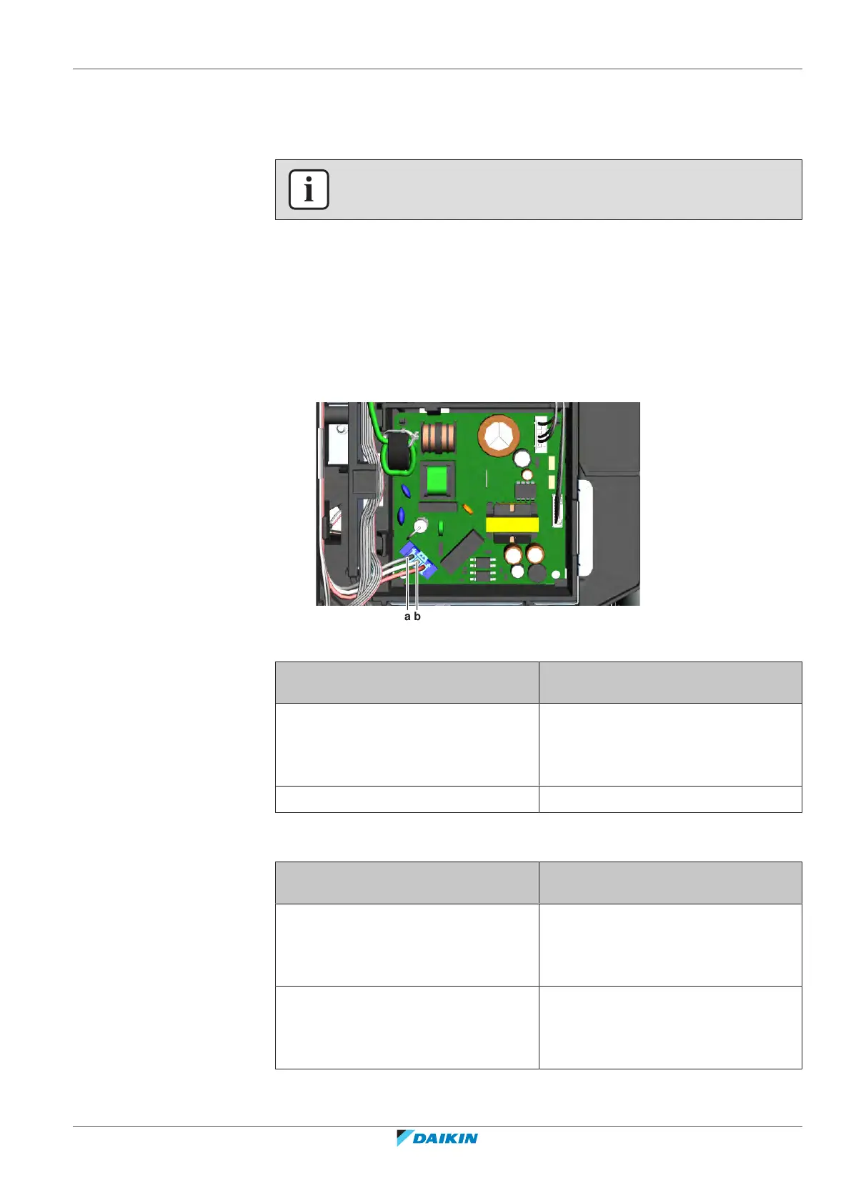
2.8 Indoor unit PCB
2.8.1 Checking procedures
INFORMATION
It is recommended to perform the checks in the listed order.
To perform a power check of the indoor unit PCB
Prerequisite: Stop the unit operation via the user interface.
Prerequisite: Turn OFF the respective circuit breaker.
Prerequisite: Remove the required plate work, see "2.13Plate work"[499].
1 Turn ON the power of the unit.
2 Measure the voltage between the black and white wires on the PCB. The
measured voltage MUST be 16VDC.
a Black wire
b White wire
Is the measured voltage on the indoor
unit PCB correct?
Action
Yes Return to "2.8.1Checking
procedures"[471] of the indoor unit
PCB and continue with the next
procedure.
No Continue with the next step.
3 Check the power supply from the outdoor unit to the indoor unit, see
"3.1.1Checking procedures"[4131].
Is the power supply from the outdoor
unit to the indoor unit correct?
Action
Yes Correct the wiring between the power
supply terminal of the indoor unit and
the indoor unit PCB, see "2.8.2Repair
procedures"[474].
No See "To check the power supply from
the outdoor unit to the indoor
unit" ("3.1.2Repair
procedures"[4132]) for the next steps.

 Loading...


