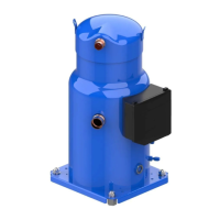
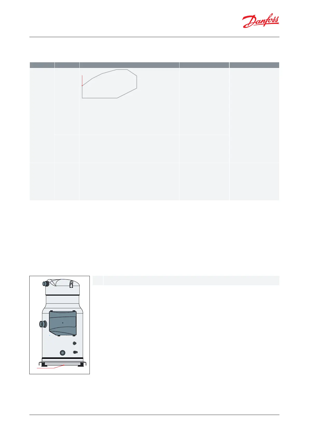
Oil temperature sensor must be placed on the bottom of the baseplate.
Test, criteria and solutions
Table 30: Test, criteria and solutions
Liquid ood back testing must be carried out under expansion
valve threshold operating conditions:
• Lowest foreseeable evaporation, and highest foreseeable
condensation.
• Minimum number of compressor running.
For reversible system, perform test in both heating and cooling
mode.
Suction superheat >5K (9°F)
and the oil superheat shall not
be more than 60 sec below the
safe limit dened in the Dilu-
tion Chart. (see Dilution Chart -
DSH090 to DSH184 R410A)
Check expansion valve se-
lection and setting.
◦ For Thermostatic ex-
pansion valve (TXV)
check bulb position...
◦ For Electronic expan-
sion valve (EXV) check
measurement chain
and PID....
Add a suction accumulator
(1)
Tests must be carried out with most unfavorable conditions :
• fan staging,
• compressor staging
• …
Oil superheat shall not be more
than 60 sec per hour below the
safe limit dened in the Dilu-
tion Chart. (see Dilution Chart -
DSH090 to DSH184 R452B /
R454B)
Check liquid
oodback dur-
ing defrost cy-
cle
Defrost test must be carried out in the most unfavorable condi-
tions (at 0°C (32°F) evaporating temperature).
Oil superheat shall not be more
than 60 sec per hour below the
safe limit dened in the Dilu-
tion Chart. (see Dilution Chart -
DSH240 to DSH600 R410A/
R452B / R454B)
Check defrost logic. In re-
versible systems, the de-
frost logic can be worked
out to limit liquid ood-
back eect. (for more de-
tails see Control logic).
Add a suction accumulator
(1)
(1)
Suction accumulator oers protection by trapping the liquid refrigerant upstream from the compressor. The accumulator should be sized at
least 50 % of the total system charge. Suction accumulator dimensions can impact oil return (gas velocity, oil return hole size…), therefore oil
return has to be checked according to section Manage oil in the circuit.
Placing oil temperature sensor
Oil temperature sensor must be placed on the bottom of the baseplate. Some thermal paste shall be used to
improve the conductivity. The sensor must also be correctly thermally insulated from the ambiance.
The Oil superheat is dened as: (Oil temperature - Evaporating temperature)
Figure 53: Placing oil temperature sensor
© Danfoss | Climate Solutions | 2022.10 AB288965961751en-001402 | 49
Scroll compressors, DSH090 to DSH600 | Application
 Loading...